


Caution. The engine stand is equipped with a self-locking mechanism. However, if the rear final drive is tilted, the self-locking mechanism may not operate. If the rear final drive turns unexpectedly, it may cause injury. Therefore, do not work on a tilted rear final drive. When turning the rear final drive over, it must be firmly supported by hand.
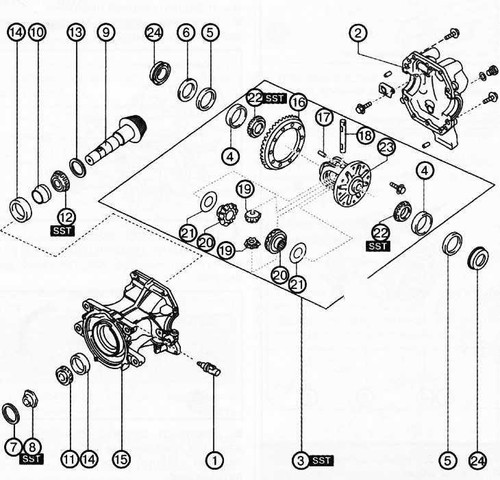
1. Rear final drive oil temperature sensor.
2. Back cover.
3. Differential assembly.
4. Outer ring of the side bearing.
5. Adjusting shims.
6. Spacer.
7. Coupling seal.
8. Lock nut.
9. Drive gear.
10. Composite spacer.
11. Inner ring of front bearing.
12. Inner ring of the rear bearing.
13. Spacer.
14. Outer bearing ring.
15. Rear main gear housing.
16. Toothed rim.
17. Pin.
18. Axle of satellites.
19. Satellites.
20. Side gears.
21. Thrust washer.
22. Inner ring of side bearing.
23. Differential box.
24. Side gear oil seal.
Note:
: replace the part with a new one after each removal.
: use a special tool or device.
: apply lubricant.
1. Remove the rear final drive oil temperature sensor.
2. Install the special device on the engine stand.
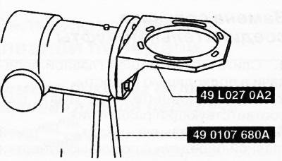
3. Install the rear final drive on a special device.
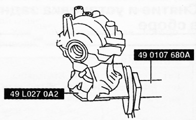
4. Remove the rear cover from the final drive housing.
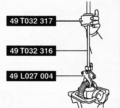
5. If the rear differential assembly cannot be removed manually, use special tools for this purpose.
6. Mark or arrange the removed left and right adjusting shims, spacers and outer rings of the side bearings in the appropriate order so as not to mix them up later during assembly.
7. Remove the coupling seal.
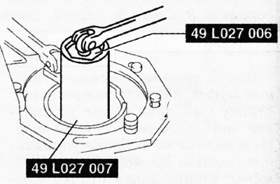
8. Remove the lock nut using a special tool.
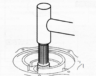
9. Remove the main gear pinion by lightly tapping it with a copper hammer.
10. Remove the composite spacer.
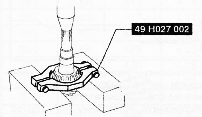
11. Remove the inner bearing rings using a special tool and a press.
12. Remove the spacer from the main gear drive pinion.
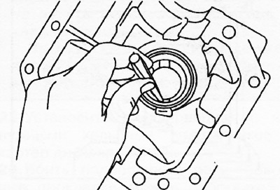
13. Remove the outer bearing race by using the two slots in the final drive housing to alternately tap the sides of the race with a copper rod.
14. Fix the differential box in a vice and unscrew the bolts.
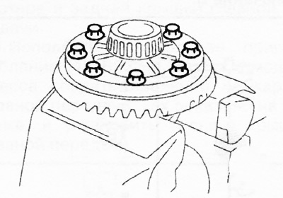
15. Lightly tap the circumference of the ring gear with a plastic hammer to remove the ring gear from the differential case.
16. Remove the pin, then extract the satellite axle and remove the satellites with side gears and thrust rings from the differential box.
Note: Mark or arrange the removed left and right side bearings in the correct order to avoid confusion during installation.
17. Using a special puller, remove the inner rings of the side bearings from the differential box.
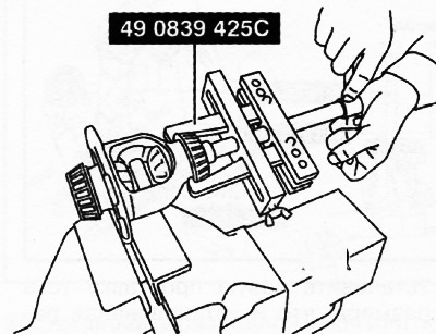
18. Remove the side gear seals.