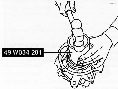
Caution. The engine stand is equipped with a self-locking mechanism. However, if the rear final drive is tilted, the self-locking mechanism may not operate. If the rear final drive turns unexpectedly, it may cause injury. Therefore, do not work on a tilted rear final drive. When turning the rear final drive over, it must be firmly supported by hand.
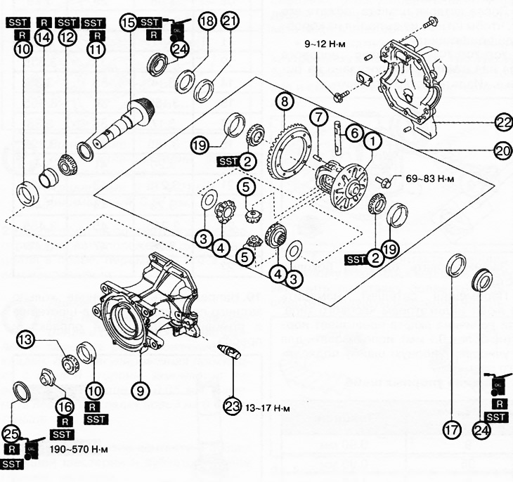
1. Differential box.
2. Inner rings of side bearings.
3. Thrust washers.
4. Side gears.
5. Satellites.
6. Axle of satellites.
7. Pin.
8. Toothed rim.
9. Rear final drive housing.
10. Outer bearing ring.
11. Spacer.
12. Inner ring of the rear bearing.
13. Inner ring of front bearing.
14. Composite spacer.
15. Main gear pinion.
16. Lock nut.
17. Left adjustment shim.
18. Spacer.
19. Outer ring of side bearing.
20. Rear differential assembly.
21. Right adjustment shim.
22. Rear cover of the main gear housing.
23. Rear final drive oil temperature sensor.
24. Side gear seals.
25. Coupling seal.
Note:
: replace the part with a new one after each removal.
: use a special tool or device.
: apply lubricant.
1. Using a suitable mandrel, press the inner races of the side bearings onto the differential case.
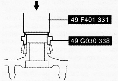
Attention: Do not confuse the left and right side bearings.
2. Assemble the side gears, thrust washers and satellites into the differential box, install the satellite axle and insert the pin.
3. After inserting the pin, tighten it so that the pin does not fall out of the differential box.
4. Install the dial indicator on the satellite as shown in the figure.
[The article is copied from the website: MazBook]
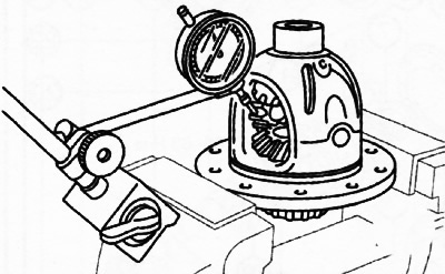
5. Fix one of the side gears.
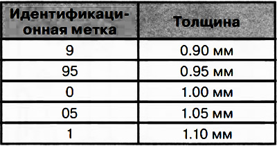
6. While moving the satellite, measure its play with a dial indicator. If the play exceeds the norm, (no more than 0.1 mm), use a thrust washer of the appropriate size for adjustment.
Thrust washers thickness
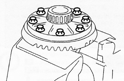
7. Align the marks applied to the ring gear and differential box during disassembly and tighten the mounting bolts in a diagonal sequence to a torque of 69-83 Nm.
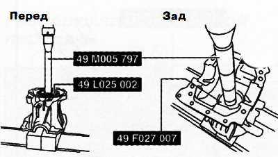
8. Using a suitable mandrel and press, press the outer bearing rings into the final drive housing.
9. Install a new spacer of the same size as the one previously installed.
10. Press the inner race of the rear bearing onto the pinion shaft using a suitable mandrel and press.
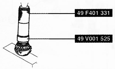
11. Apply final drive oil to the new lock nut.
12. Assemble the new composite spacer, front bearing inner race and spacer onto the pinion shaft and tighten the lock nut.
13. Turn the threaded part of the gear shaft by hand to seat the bearing.
14. Tighten the lock nut to the lower limit of the specified torque range (190-570 Nm), thus creating the necessary preload. If the necessary preload (0.9-1.6 Nm) is not ensured, replace the composite spacer and check the preload value again.
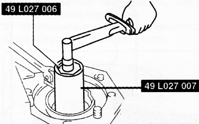
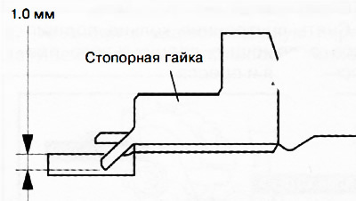
15. Tighten the lock nut using a chisel and hammer.
16. Install the rear final drive housing on a special device on the engine stand.
17. Install the spacer on the rear final drive housing.
18. Place the differential case with the outer races of the side bearings on a flat surface as shown in the figure and measure the height with a caliper and straight edge. This is value A.
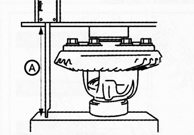
19. Measure the width of the installed differential in the main gear housing with the installed spacer. This is value B.
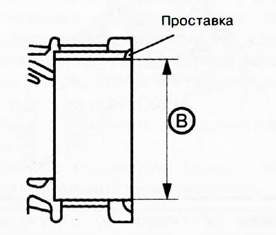
20. The total thickness of the left and right adjusting shims is determined by the following formula.
- C ₁ = B-A+0.16 mm
- C ₂ = B-A+0.25 mm
21. If the total thickness of previously installed shims is between the values of C ₁ and C ₂, use these shims.
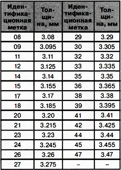
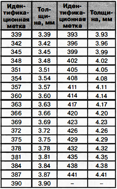
22. If the total thickness of the previously installed shims does not fall within the range between C ₁ and C ₂, the adjusting shims must be replaced by selecting two suitable adjusting shims from the following table.
Thickness of adjusting shims
Attention.
- If adjusting shims are reused, do not confuse left and right shims.
- Do not confuse the left and right outer rings of the side bearings and spacers.
23. Install the differential with the outer bearing rings into the differential housing.
24. Drive the selected adjusting linings between the spacer and the bearing ring with a plastic hammer.
25. Clean the contact surfaces of the crankcase and the rear cover of the main gear.
26. Using a special device (49 8032 335A), using a press, apply pressure to the main gear housing as shown in the figure and install the rear cover of the main gear.
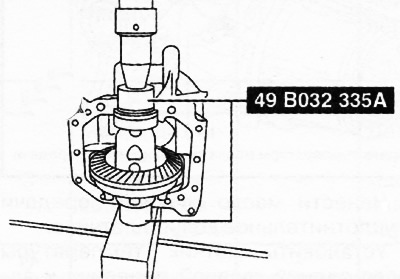
Caution: Do not apply more than 2 t of force.
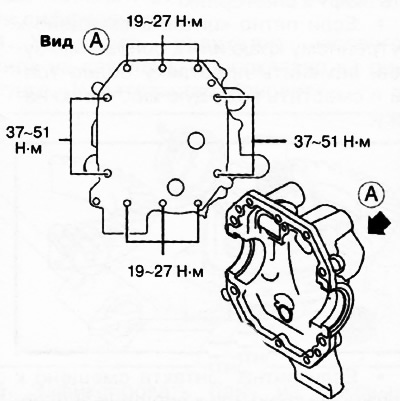
27. Install the bolts and tighten them to the torques shown in the figure.
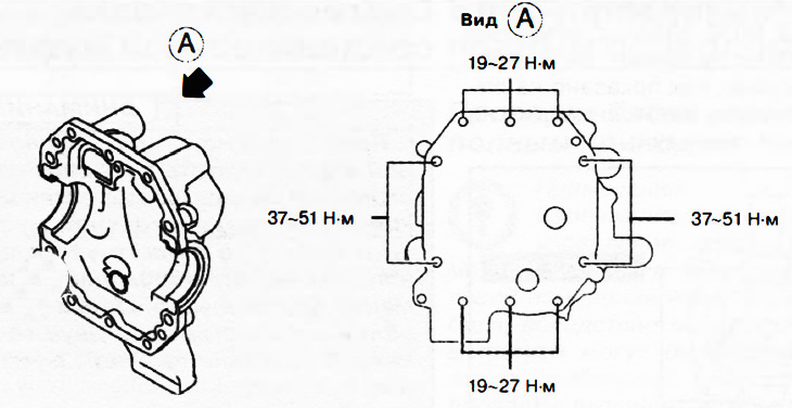
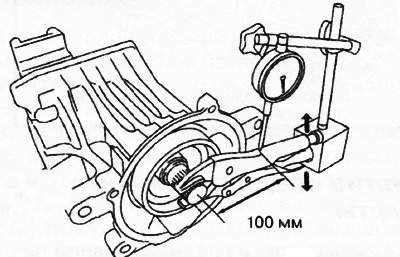
28. Place an adjustable wrench or similar tool on the spline of the gear shaft as shown in the figure and measure the clearance at a distance of 100 mm from the center of the shaft.
Note:
Backlash of the rear main gear shaft-pinion:
- Standard: 0.13-0.21 mm.
- Minimum: 0.07 mm.
29. If the clearance is not within the norm, adjust the position of the differential assembly by moving it in the axial direction.
Note: When moving the differential assembly axially, replace the adjusting shims. If the adjusting shim on the right side is replaced with a new one that is 0.05 mm thicker, replace the left shim with a new one that is 0.05 mm thinner.
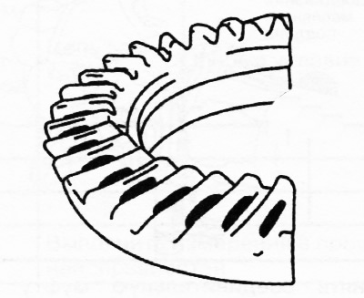
30. Check the contact patch in the teeth of the drive gear and the main gear ring gear:
- Apply a thin, even layer of paint to both surfaces of the gear ring.
- Turn the ring gear back and forth several times by hand and check the spot in the engagement of the teeth.
- Check the contact pattern in the engagement of the teeth at four points around the circumference of the gear ring to ensure that the contact pattern position is normal everywhere. If the contact pattern is normal, remove the paint from the teeth. If the contact pattern is displaced, adjust the height of the pinion gear, and then adjust the backlash in the gears.
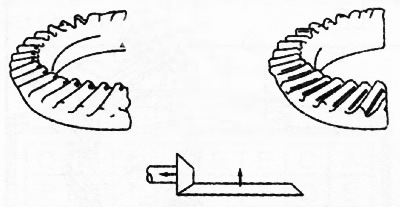
- If the contact patch is shifted to the inner edge or to the base of the teeth, replace the spacer with a thinner one and shift the pinion gear outward.
 |
 |
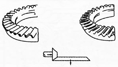
If the contact patch is shifted to the outer edge or to the top of the teeth, replace the spacer with a thicker one and shift the pinion gear inward.
31. If the clearance in the gears is normal and the contact patch position is normal, install the rear cover of the main gear.
Attention.
- Before applying new sealant, carefully remove any remaining old sealant.
- Install the rear cover onto the final drive housing before the applied sealant begins to harden.
- After assembling the rear final drive, wait at least 30 minutes before adding oil to allow the sealant to cure properly.
32. Clean the contact surfaces of the crankcase and rear cover and apply a thin layer of sealant.
33. Using a special device (49 8032 335A), using a press, create pressure on the main gear housing as shown in the figure, and install the rear cover on the main gear housing.
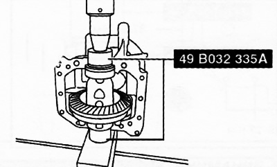
Caution: Do not apply more than 2 t of force.
34. Install the bolts and tighten them to the torques shown in the figure.
35. Apply final drive oil to the lips of the new side seal and install the seal using a suitable drift.

36. Apply final drive oil to the lips of the new coupling seal and install the seal using a suitable drift.