
Terminal identification and continuity test (between terminals 2 and 3) Cruise Control Switch - Ford Probe Models
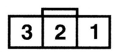
| Switch position | Resistance (Ohm) |
| On | 10000 |
| Off | Less than 5 |
| Set/Acc | 680 |
| Coast | 120 |
| Resume | 2200 |
Cruise Control Master Switch Terminal Identification - Mazda Models

When switched on, there must be continuity between terminals C and D.
Mazda Cruise Control Trouble Codes
| Code | Possible reason |
| 1 | Connecting wires, system drive, brake light switch |
| 5 | Fuse |
| 7 | Stoplight switch |
| 11 | Cruise control switch |
| 15 | Electronic control unit |
Examination
1. Check the cruise control system fuse.
2. Check the operation of the brake light switch.
3. Check the operation of the switch on the clutch pedal.
4. Inspect the vacuum hoses and check the system cable tension.
5. Check speed sensor.
Cruise control switches
Check and replacement
Models of Ford Probe
1. Remove the switches and test them for continuity (see fig. Terminal identification and continuity test (between terminals 2 and 3) Cruise Control Switch - Ford Probe Models).
2. Remove the air bag module.
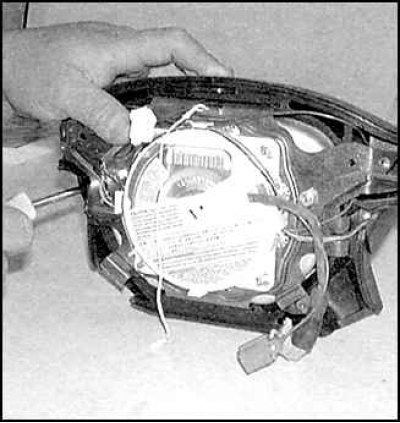
3. Unscrew the mounting screws, disconnect the connection connectors and remove the switches.
4. Installation is carried out in the reverse order of removal.
Mazda Models
On these models, the cruise control system has a built-in diagnostic system.
1. To activate the diagnostic system, turn on the ignition and press the Resume/Accel button for three seconds.
2. Two seconds later, after the cruise control system warning light on the instrument panel goes off, a fault code will be displayed (see table. Mazda Cruise Control Trouble Codes).
3. Remove the cruise control system switch and check it for continuity (see fig. Cruise Control Master Switch Terminal Identification - Mazda Models).
4. To replace the switch located on the steering column, see paragraphs (see table. Mazda Cruise Control Trouble Codes).
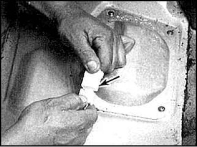
5. To replace the main cruise control switch, remove the switch from the instrument panel and disconnect the connector.
6. Installation is carried out in the reverse order of removal.
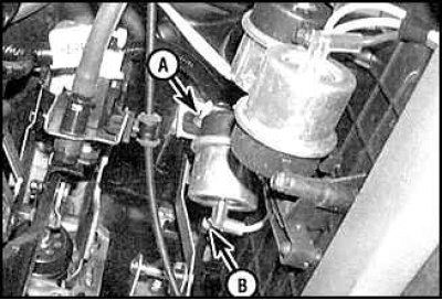
Cable tension adjustment
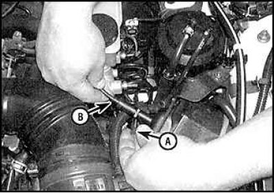
Remove mounting clip (A) and adjust the cable tension so that it has 3 mm free play at the point (IN).