Removal and installation of the hydroelectronic control unit
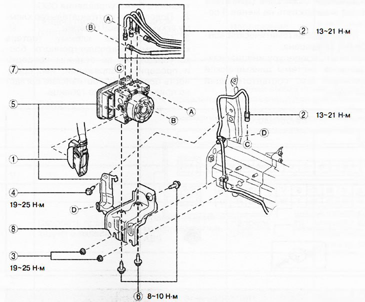
1. DSC hydro-electronic unit connector.
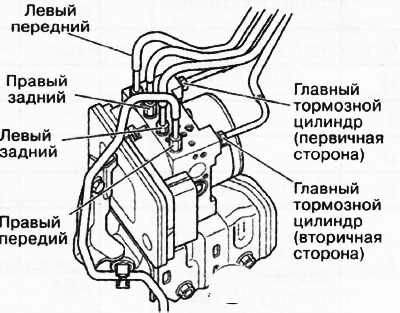
2. Brake pipelines.
3. Nuts.
4. Bolt.
5. Hydroelectronic control unit DSC assembled.
6. Bolts.
7. Hydroelectronic control unit.
8. Bracket.
Attention.
- If the configuration of the hydro-electronic control unit is not completed, the vehicle may be involved in an accident due to incorrect operation of the system. If the DSC hydro-electronic control unit is replaced with a new one, it is imperative to use the automatic configuration function to create the correct operating state of the stability control system.
- If the stability control system sensors initialization procedure is not completed, the system will not operate correctly and may cause an accident. After replacing or removing the hydroelectronic control unit, it is imperative to perform the procedure for initializing the sensors of the dynamic stabilization system to ensure proper system operation.
- If the hydro-electronic control unit falls from a height, its internal parts may be damaged. Be careful not to drop the hydro-electronic unit. Replace a hydro-electronic control unit that has been hit or dropped with a new one.
Note:
- When the ignition is switched on or the engine is started after replacing the hydro-electronic stability control control unit, the system control unit reads data from the instrument cluster via the CAN bus to perform automatic configuration.
- The dynamic stability control hydro-electronic control unit stores vehicle-specific information that must be recorded using a diagnostic tool before replacing the unit.
- The new hydroelectronic control unit for the dynamic stabilization system does not contain any information.
1. Remove the decorative engine cover.
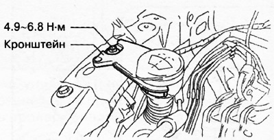
2. Disconnect the engine control unit connector (from the front of the car) and remove the wiring bracket from the #3 engine mount. Move the wiring harness to the engine control unit to the side.
3. Remove the bracket.
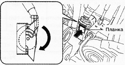
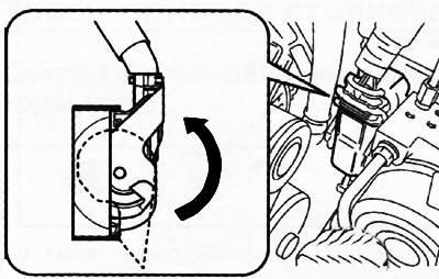
4. Pull the locking lever down in the direction of the arrow in the illustration while pressing the tab on the connector cover.
5. Pull the connector towards the rear of the vehicle and remove it.
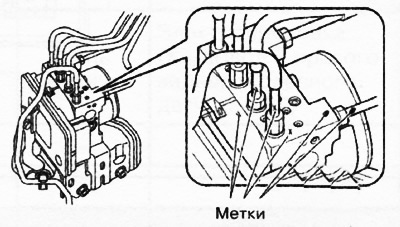
6. Apply alignment marks to the brake lines and the hydro-electronic control unit.
7. Tape the connectors to prevent brake fluid from getting into them.
8. Disconnect the brake lines.
9. Unscrew the bolts and nuts securing the bracket and remove the hydroelectronic control unit assembly with the bracket.
10. Unscrew the fastening bolts and remove the hydro-electronic unit from the bracket.
11. Installation is carried out in the reverse order of removal, taking into account the following:
Install the brake pipes on the hydro-electronic unit, aligning the alignment marks made before removal.
Tighten the brake pipes to the specified tightening torque using a special wrench for flange union nuts.
Connect the connector and pull the locking lever up in the direction of the arrow in the illustration.
After connecting the connector, make sure that its cover is fully pressed in.
12. After installation, add brake fluid to the reservoir, remove air from the brake system and check the brake fluid level in the reservoir again.
13. Perform the following procedure to carry out automatic configuration of the DSC hydro-electronic control unit:
- Turn on the ignition (engine off) and wait at least 10 seconds.
- Switch off the ignition and wait at least 3 seconds.
- Turn on the ignition (engine off) and wait at least 3 seconds.
- The automatic configuration procedure is completed.
14. Perform the procedure for initializing the sensors of the dynamic stabilization system (see related section below).
15. Perform the procedure for initializing the tire pressure monitoring system (see chapter "Suspension").
16. Delete trouble codes from the car's memory.
Checking the hydroelectronic control unit DSC
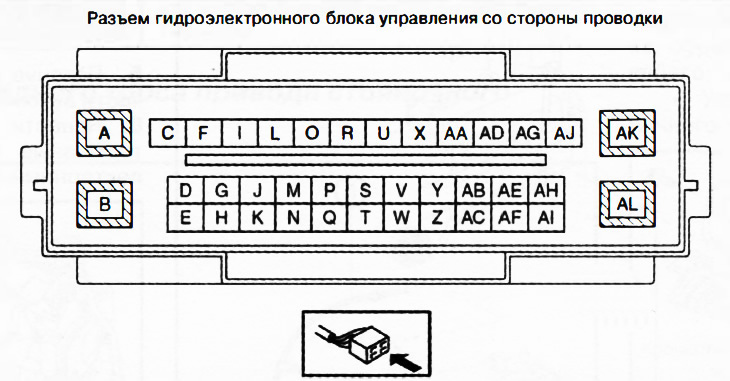
1. Disconnect the DSC hydro-electronic control unit connector.
2. Connect the negative battery terminal.
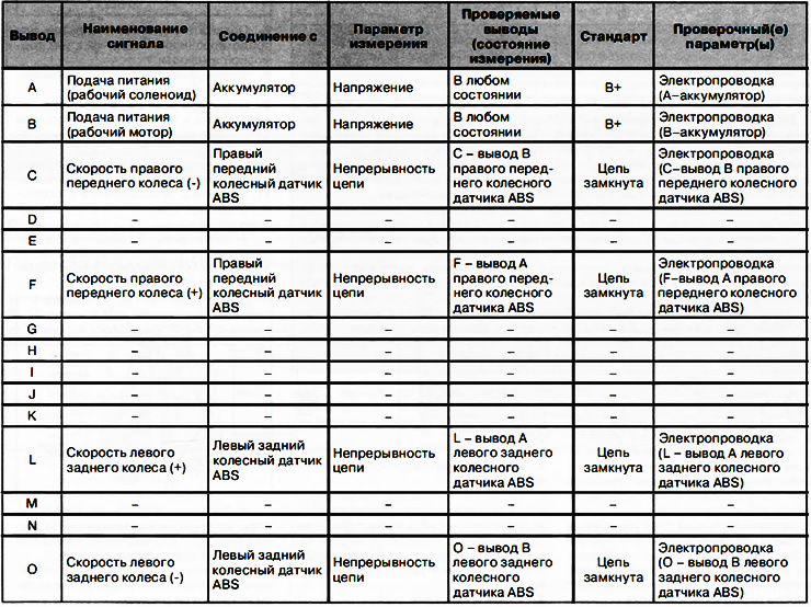
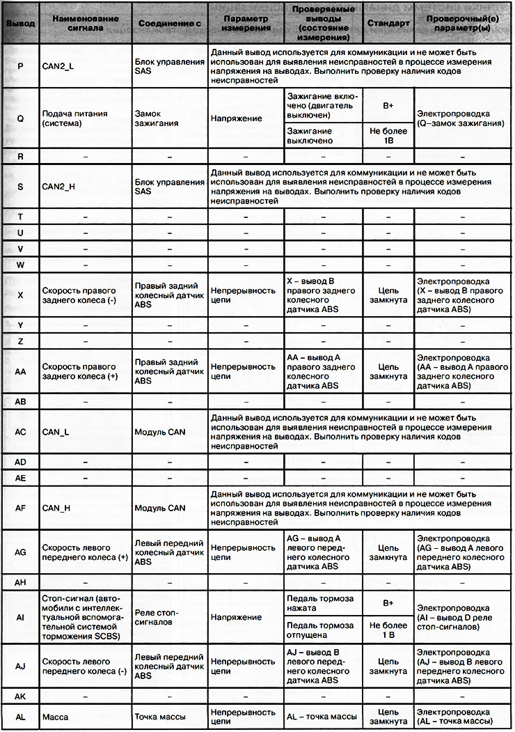
3. Connect the tester terminal to the wiring side connector of the hydro-electronic control unit and check the voltage, continuity or resistance according to the table below.