


Checking the vacuum pump
1. Remove the decorative engine cover.
2. Open the clamp with pliers and disconnect the vacuum hose from the vacuum pump.
3. Install a vacuum gauge as shown in the figure and check the vacuum.
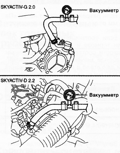
4. Warm up the engine. If the pressure is less than normal, check the technical condition of the vacuum pump and the lack of oil in the pump.

5. Installation is made in an order, the return to removal.
Removal and installation of the vacuum pump
Versions with petrol engines
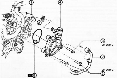
1. Vacuum hose.
2. Connector for the exhaust camshaft position sensor.
3. Bolt.
4. Vacuum pump.
5. O-ring of circular cross-section.
Note:replace the part with a new one after each removal.
1. Remove the decorative engine cover.
2. Remove the battery from the shelf.
3. Remove the electrical wiring of the engine control unit to the side.
4. Open the clamp with pliers and disconnect the vacuum hose from the vacuum pump.
5. Disconnect the exhaust camshaft position sensor connector.
6. To turn away bolts of fastening and to remove the vacuum pump.
Note: When removing the vacuum pump, place a rag under its mounting surface so that the engine oil that runs out does not fall on other parts.
7. Remove the O-ring.
8. Turn the vacuum pump by hand to drain any remaining engine oil from the vacuum pump.
9. Degrease the O-ring groove and mounting surfaces.
10. Install a new O-ring on the vacuum pump.
11. Install the vacuum pump.
12. Further installation is carried out in the reverse order of removal.
Versions with diesel engines
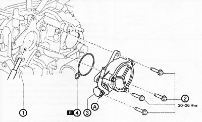
1. Vacuum connection.
2. Mounting bolts.
3. Bolt.
4. Vacuum pump.
A. O-ring of circular cross-section.
Note:replace the part with a new one after each removal.
1. Remove the decorative engine cover.
2. Remove the battery from the shelf.
3. Open the clamp with pliers and disconnect the vacuum hose from the vacuum pump.
4. Remove the following parts:
- air filter cover.
- Air filter element.
- Air duct.
- Air filter housing.
- Air hose.
- Air inlet.
5. Remove the turbocharger outlet hose together with the air inlet.
6. Disconnect the fuel temperature sensor connector.
7. Disconnect the camshaft position sensor connector.
8. Remove the camshaft position sensor wiring from the lower case.
9. Prepare for engine parameter checks (see chapter 6b "Mechanical part of diesel engine").
10. Unscrew the fixing bolts of the water pipe and remove it to the side.
11. Remove fuel return line (from the high pressure fuel pump).
12. Remove fuel return line (from the fuel injectors).
13. Remove fuel return hoses #1 and #2.
14. Unscrew the bolts securing the lower case and remove it to the side.
15. Disconnect the vacuum connection.
16. To turn away fixing bolts and to remove the vacuum pump.
Note: When removing the vacuum pump, place a rag under its mounting surface so that the engine oil that runs out does not fall on other parts.
17. Remove the O-ring.
18. Turn the vacuum pump by hand to drain any remaining engine oil from the vacuum pump.
19. Degrease the mounting groove for the O-ring and mounting surfaces.
20. Install a new O-ring on the vacuum pump.
21. Install the vacuum pump.
22. Apply a thin layer of silicone sealant (TB1217G), as it shown on the picture.
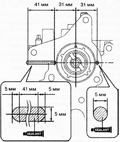
Note: Install the vacuum pump before the sealant begins to harden.
23. Install the vacuum pump.
24. Further installation is carried out in the reverse order of removal.
25. Perform post-engine maintenance procedures (see chapter 6b "Mechanical part of diesel engine").