
MazBook.ru
English Русский
Български
Беларускі
Український
Српски
Hrvatski
Română
Polski
Slovenský
Magyar
• Bookmark • Sitemap • Contacts •   
Cars Opel Cars Ford Cars Volkswagen Cars Audi Cars Kia Cars Renault Cars Peugeot


Familia Capella Mazda3 Mazda6 CX-? Others Articles
Mazda 121 (3) (1996-2003) Mazda BT-50 (1) (2006-2011)

Upper cover and crankcase extension (Mazda BT-50 (1))

  • Home
  • Mazda
  • BT-50 J97M (2006-2011)
  • Transmission
  • Mechanical gearbox
  • Upper cover and crankcase extension
0
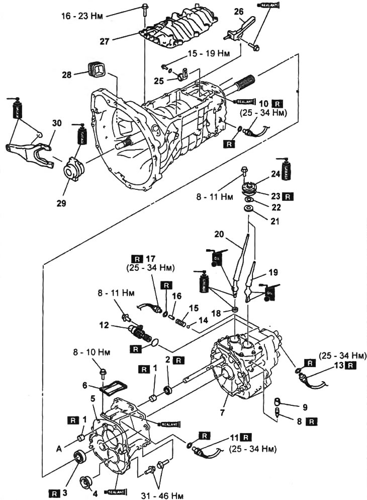
Removal and installation of parts should be carried out using the assembly drawing "Top cover and crankcase extension".

Upper cover and crankcase extension.

Upper cover and crankcase extension.
1 - bushing,
2 - control rod seal,
3 - oil seal of the crankcase extension,
4 - funnel,
5 - crankcase extension,
6 - sealing cover,
7 - transfer case,
8 - breather,
9 - breather boot,
10 - reversing light switch,
11 - neutral gear engagement sensor,
12 - speed sensor,
13 - all-wheel drive engagement sensor,
14 - steel ball,
15 - spring,
16 - sensor pin,
17 - transfer case neutral gear engagement sensor,
18 - gearbox control lever seat,
19 - transfer case control lever,
20 - gearbox control lever,
21 - bushing,
22 - washer,
23 - gasket,
24 - anther,
25 - control rod tip,
26 - oil drain,
27 - top cover,
28 - case,
29 - clutch release bearing,
30 - clutch release fork.


Notes on removal


1. Crankcase extension oil seal.
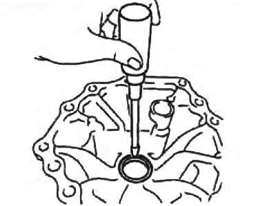
1. Crankcase extension oil seal.


2. Top cover.


Using a slotted screwdriver positioned as shown in the figure, pry the top cover off and then remove it.
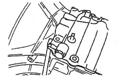
Using a slotted screwdriver positioned as shown in the figure, pry the top cover off and then…


3. Crankcase extension.

Using a slotted screwdriver positioned as shown in the illustration, disconnect the crankcase extension and then remove it.
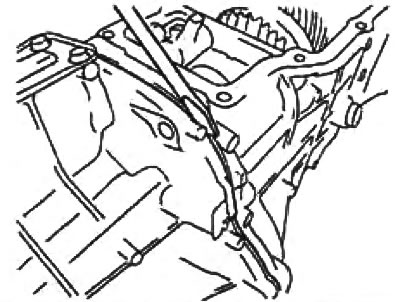
Using a slotted screwdriver positioned as shown in the illustration, disconnect the crankcase…


4. Control rod seal.

Using a slotted screwdriver, remove the oil seal.
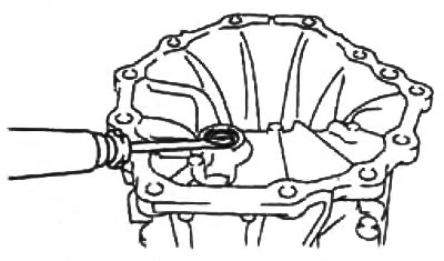
Using a slotted screwdriver, remove the oil seal.


5. Sealing cover.


Using drifts and a hammer, remove the sealing cover.

Note: Only remove the sealing cap if it is faulty and you intend to replace it.
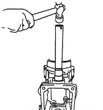

Note: Only remove the sealing cap if it is faulty and you intend to replace it.


6. Bushing.

Using a mandrel and a hammer, remove the bushings.
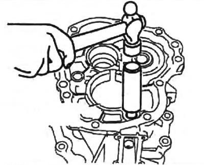
Front hub.
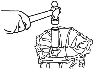
Front hub.


Rear hub.

Rear hub.


Using a slotted screwdriver, remove the oil seal.

Installation Notes

1. Bushing.
Using drifts and a hammer, set the front and rear bushings to the specified depth.
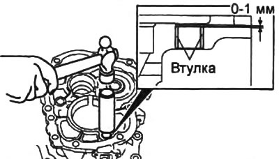


Front hub.
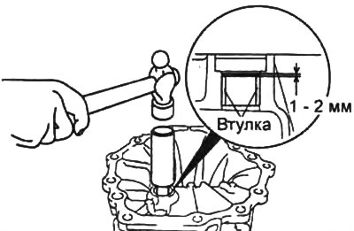
Front hub.


Rear hub.

Rear hub.


2. Control rod seal.

a) Apply grease to the sealing lip of the oil seal.

b) Using a drift and hammer, install the seal as shown in the figure.
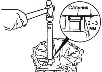
b) Using a drift and hammer, install the seal as shown in the figure.


3. Sealing cover.

Using drifts and a hammer, install the sealing cover as shown in the figure.
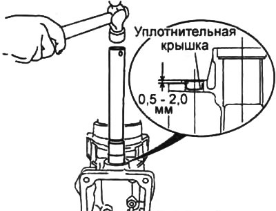
Using drifts and a hammer, install the sealing cover as shown in the figure.


4. Crankcase extension seal.


a) Apply grease to the sealing lip of the oil seal.

b) Using mandrels and a hammer, install the seal as shown in the figure.

5. Crankcase extension.

a) Apply sealant to the contact surface of the housing extension and the gearbox housing.
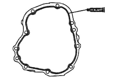
a) Apply sealant to the contact surface of the housing extension and the gearbox housing.


b) Install the crankcase extension onto the gearbox.
  • Tightening torque - 31 - 46 Nm

Note: Installation must be completed within 30 minutes after applying the sealant. Otherwise, remove the applied sealant and repeat the procedure again.


6. Top cover.

a) Apply sealant to the contact surface of the top cover as shown in the figure.
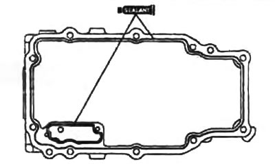
a) Apply sealant to the contact surface of the top cover as shown in the figure.


b) Install the top cover onto the gearbox.
  • Tightening torque - 16 - 23 Nm

Note: Installation must be completed within 10 minutes after applying the sealant. Otherwise, remove the applied sealant and repeat the procedure again.


7. Sealing cover.

a) Apply sealant to the contact surface of the sealing cover as shown in the figure.
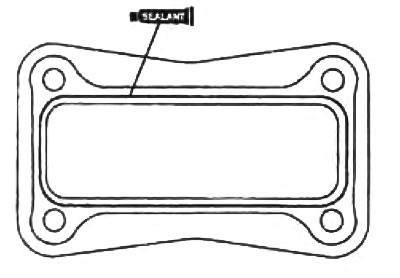
a) Apply sealant to the contact surface of the sealing cover as shown in the figure.


b) Install the sealing cover on the gearbox.
  • Tightening torque: 8-10 Nm

Note: Installation must be completed within 10 minutes after applying the sealant. Otherwise, remove the applied sealant and repeat the procedure again.


8. Breather.

Install the breather using a mandrel and a hammer.
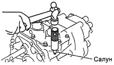
Install the breather using a mandrel and a hammer.


9. Clutch release fork and release bearing.

Before installing the clutch release fork and release bearing, apply grease to the surfaces shown in the figure.
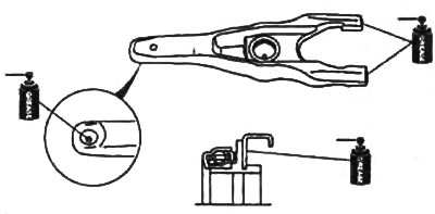
Before installing the clutch release fork and release bearing, apply grease to the surfaces shown…
This article is available at: russian, bulgarian, belarusian, ukrainian, serbian, croatian, romanian, polish, slovak, hungarian
This text was checked by: Vladimir Bazhenov
Share with friends on social networks:

Previous
Mazda BT-50 (1) » Mechanical gearbox
Next

Gearbox assembly — precautions for disassembly and assembly
Gearbox assembly — removal and installation
Neutral gear engagement sensor
Checking the oil level and changing it
Fifth gear and reverse gears
Removal and installation gearbox shafts
Disassembly and assembly of gearbox shafts
Gear shift mechanism
Checking gearbox components
More articles on repairing other Mazda models
Luggage compartment cover Mazda Capella 3 (1982-1992, petrol)
Raising the rear edge of the hatch cover Mazda3 BK (2003-2009)
Raising the rear edge of the hatch cover Mazda6 GG (2002-2008)
Removal and installation the decorative engine cover Mazda CX-5KE (2012-2017)
Link in different formats to this article
Comments and feedback from visitors
No comments yet


How much will 40 + 23 ?


Mazda BT-50 (1) (2006-2011) 
  • General information
  • Introduction to guide
  • User manual
  • Maintenance
  • Power unit
  • Engine repair (diesel)
  • Cooling and lubrication system
  • Fuel injection system
  • Intake and exhaust system
  • Engine electrical equipment
  • Transmission
  • Clutch
  • Mechanical gearbox
  • All-wheel drive system
  • Transfer case and gearboxes
  • Chassis
  • Front suspension
  • Rear suspension
  • Steering
  • Brake system
  • Body
  • Exterior (external elements)
  • Interior (internal elements)
  • Heating and air conditioning
  • Security system SRS
  • Electrical equipment
  • Equipment and devices
  • Electrical circuits
Mazda 121 (3) (1996-2003) 
  • General information
  • User manual
  • Maintenance
  • Power unit
  • Petrol engine 1.3 l
  • Petrol engine 1.25/1.4 l
  • Diesel engine
  • Lubrication system
  • Cooling system
  • Ignition system
  • Supply system
  • Fuel injection (gasoline)
  • Fuel injection (diesel)
  • Exhaust system
  • Transmission
  • Clutch
  • Car gearbox
  • Chassis
  • Front suspension
  • Rear suspension
  • Steering
  • Brake system
  • Wheels and tires
  • Body
  • Exterior (external elements)
  • Interior (internal elements)
  • Doors, windows and locks
  • Heating system
  • Electrical equipment
  • Troubleshooting
  • Equipment and devices
  • Lighting system
  • Power devices
  • Electrical circuits
MazBook.ru © 2018–2026 · Mobile version · Articles and news · Sitemap: EN BG BY UA RS HR RO PL SK HU · Feedback · Site search · Add to bookmarks Familia 5 (BF) · Familia 6 (BG) · Capella 3 (GC) · Capella 3 and 4 (GC) · Capella 4 (GD) · Capella 5 (GE) · Capella 6 (GF) · Mazda3 BK · Mazda6 GG · CX-5KE · Mazda 121 (3) · Mazda BT-50 (1) ·
By continuing to use the site, you agree to the use of cookies 🔐