
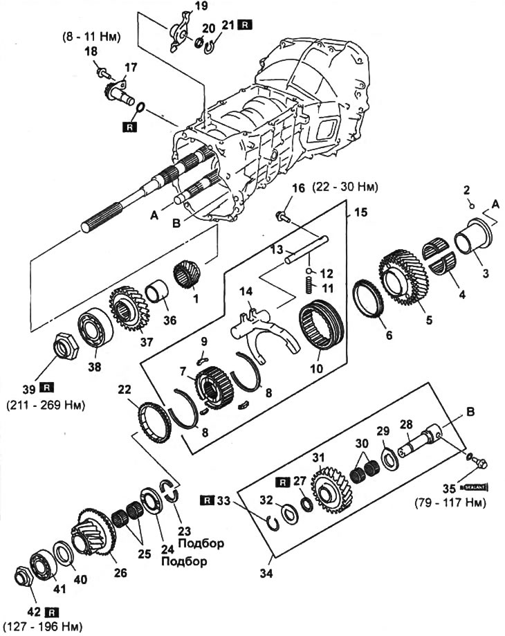
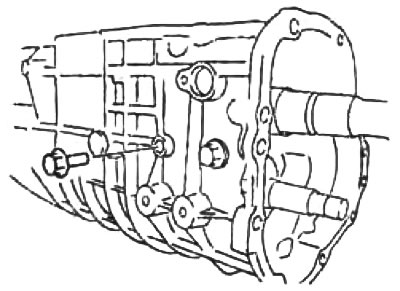
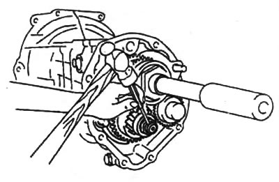
5th and reverse gears.
1 - fifth gear driven gear,
2 - steel ball,
3 - the inner ring of the fifth gear drive gear bearing,
4 - needle bearing of the drive gear of the fifth gear,
5 - fifth gear drive gear,
6 - synchronizer ring,
7 - hub synchronizer of fifth gear and reverse gear,
8 - crackers spring,
9 - crackers,
10 - synchronizer clutch,
11 - spring,
12 - steel ball,
13 - fifth gear and reverse gear engagement rod,
14 - fork for engaging the fifth gear and reverse gear,
15 - synchronizer and fork for engaging the fifth gear and reverse gear,
16 - locking bolt,
17 - intermediate lever shaft,
18 - locking bolt,
19 - intermediate lever,
20 - puck,
21 - retaining ring,
22 - synchronizer ring,
23 - thrust washer,
24 - spacer,
25 - needle bearing of the drive gear of the reverse gear,
26 - reverse drive gear,
27 - friction damper,
28 - shaft of the intermediate gear of the reverse gear,
29 - thrust washer,
30 - needle bearing of the intermediate gear of the reverse gear,
31 - intermediate reverse gear,
32 - thrust washer,
33 - retaining ring,
34 - intermediate gear and reverse gear shaft,
35 - locking bolt,
36 - spacer,
37 - driven gear reverse gear,
38 - rear bearing of the secondary shaft,
39 - nut,
40 - thrust washer,
41 - rear intermediate shaft bearing,
42 - nut.
Note: when assembling, it is necessary to select the dimensions of the parts indicated in the assembly drawing by the inscription "Selection".
Withdrawal Notes
1. Nuts of the secondary and intermediate shafts.
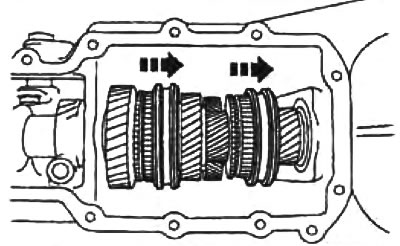
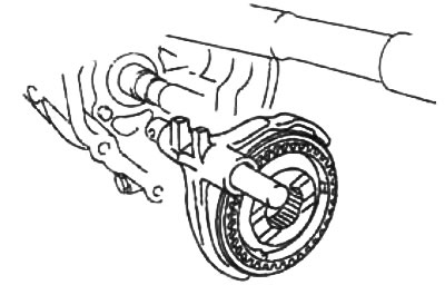
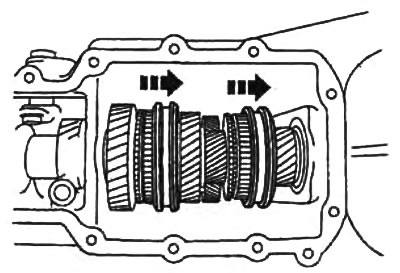
A) Move the synchronizer clutches as shown in the figure to engage second and fourth gears at the same time.
b) Loosen the intermediate shaft nut by turning it clockwise.
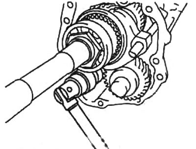
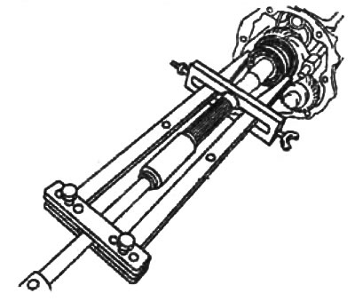
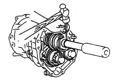
V) Using the special tool, unscrew the output shaft nut by turning it counterclockwise.
2. Rear output shaft bearing. Using a puller, remove the rear output shaft bearing.
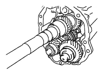
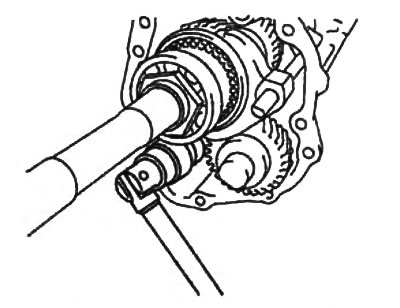
3. Intermediate gear and reverse gear shaft.
Loosen the lock bolt and remove the intermediate gear and reverse gear shaft assembly.
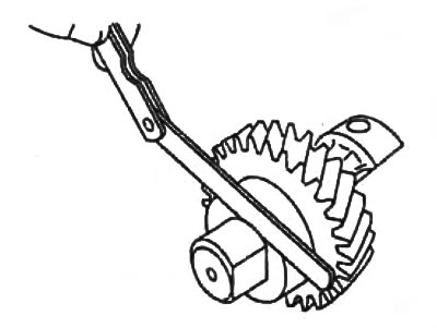
4. Friction damper for reverse idle gear. Remove the reverse idler gear friction damper using a slotted screwdriver.
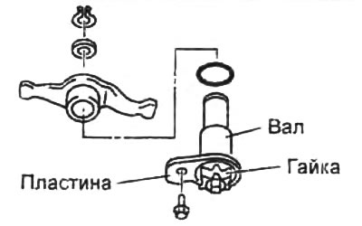
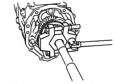
5. Intermediate lever.
To prevent displacement of the intermediate lever shaft, do not loosen the nut while removing the intermediate lever.
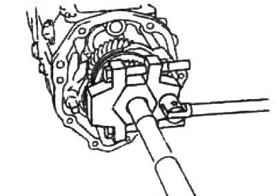
6. Fork of inclusion of the fifth transfer and transfer of a backing.
A) Turn away a lock bolt of a rod of inclusion of the fifth transfer and transfer of a backing.
b) Remove the fork assembly with the stem and synchronizer.
Installation Notes
1. 5th gear inner bearing race,
A) Install the steel ball on the intermediate shaft.
b) Align the groove on the bearing inner race with the ball and install the bearing inner race.
2. 5th gear drive gear, synchronizer and fork,
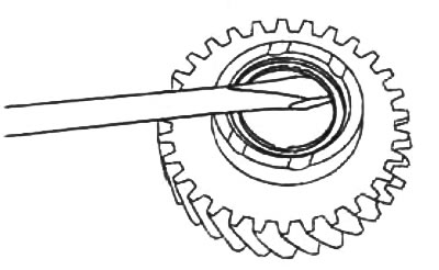
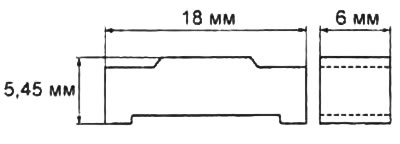
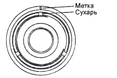
A) To assemble the synchronizer, align the grooves on the synchronizer rings with crackers.
Note: standard sizes of crackers are shown in the figure.
b) Align the mark on the synchronizer hub with the cracker as shown in the figure.
V) Install the synchromesh and the 5th/Reverse shift fork into the transmission.
G) Screw in the lock bolt for the fifth gear and reverse gear.
- Tightening torque - 22 - 30 Nm
d) Install thrust washer.
e) Measure the clearance between the thrust washer and the intermediate shaft groove.
- Gap - 0 - 0.05 mm
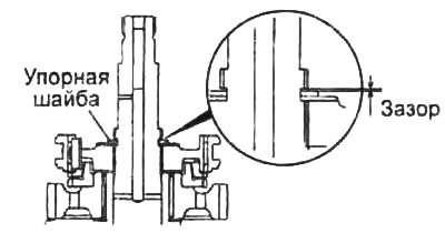
If necessary, adjust the thickness of the thrust washer to ensure the specified clearance.
Note: Thrust washers are available in thicknesses from 3mm to 3.4mm in 3.30mm increments.
3. Reverse drive gear.
A) Measure distances "A" And "IN", shown in the figure.
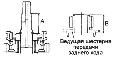
b) Calculate magnitude "WITH" according to the formula:
C \u003d A - B, where
C - the distance between the synchronizer hub and the reverse gear,
B - the height of the reverse gear drive gear,
A is the distance between the synchronizer hub and the thrust washer.
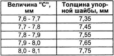
A) According to the table, select the thickness of the thrust washer to ensure the specified clearance.
- Gap - 0.25 - 0.35 mm
G) Install thrust washer.
d) Install the reverse drive gear.
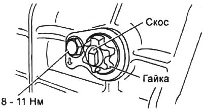
4. Shaft of the intermediate lever. Install the intermediate lever shaft.
- Tightening torque - 8-11 Nm
Note:
- If the relay arm shaft has been replaced or the shaft nut has been loosened, install the shaft so that the bevel on the shaft is pointing up.
- Apply sealant to the threads of the nut.
- If the engagement stroke of the third and fourth gears is not correct, loosen the nut and repeat the adjustment.
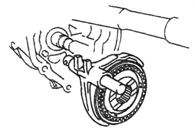
5. Intermediate gear and reverse gear shaft.
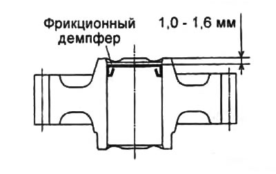
A) Using drifts and a hammer, install the friction damper.
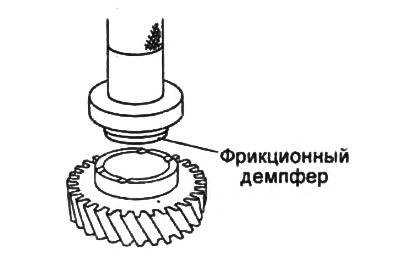
b) Make sure the damper is installed as shown in the picture. Adjust the installation depth if necessary.
V) Install the gear on the shaft.
G) Measure the clearance between snap ring and thrust washer.
If necessary, select the thickness of the retaining ring to ensure the specified clearance.
- Gap - 0.1 - 0.2 mm
Note: Retaining rings are available in thicknesses from 1.5mm to 1.9mm in 0.1mm increments.
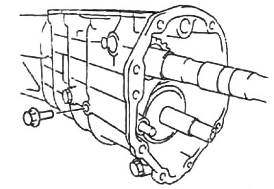
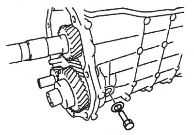
d) Install the intermediate gear and shaft assembly into the gearbox housing.
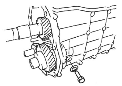
e) Install the reverse gear shaft retainer bolt.
- Tightening torque - 79 - 117 Nm
6. Nuts and bearings of the secondary and intermediate oxen.
O) Move the synchronizer clutches as shown in the figure to engage second and fourth gears at the same time.
b) Install the secondary and intermediate shaft bearings and screw on the nuts.
V) Using the special tool, tighten the output shaft nut.
- Tightening torque - 211 - 269 Nm
G) Install the intermediate shaft nut by turning it counterclockwise.
- Tightening torque - 126 - 196 Nm
d) Using a punch, lock the nuts of the secondary and intermediate shafts.
secondary shaft.
intermediate shaft.