MazBook.ru
English Русский
Български
Беларускі
Український
Српски
Hrvatski
Română
Polski
Slovenský
Magyar
• Bookmark • Sitemap • Contacts •   
Cars Opel Cars Ford Cars Volkswagen Cars Audi Cars Kia Cars Renault Cars Peugeot


Familia Capella Mazda3 Mazda6 CX-? Others Articles
Mazda 121 (3) (1996-2003) Mazda BT-50 (1) (2006-2011)

Disassembly and assembly of gearbox shafts (Mazda BT-50 (1))

  • Home
  • Mazda
  • BT-50 J97M (2006-2011)
  • Transmission
  • Mechanical gearbox
  • Disassembly and assembly of gearbox shafts
0
Contents: Notes on removal ⇓ Installation Notes ⇓
Removal and installation of parts should be carried out using the assembly drawing "Disassembly and assembly of gearbox shafts".
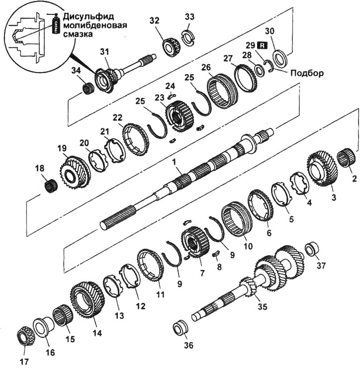
Disassembly and assembly of gearbox shafts.

Disassembly and assembly of gearbox shafts.
1 - secondary shaft,
2 - needle bearing of the driven gear of the second gear,
3 - driven gear of the second gear,
4 - internal conical ring of the synchronizer,
5 - double conical synchronizer ring,
6 - synchronizer ring,
7 - hub of synchronizer of first and second gears,
8 - crackers,
9 - cracker spring,
10 - first and second gear synchronizer clutch,
11 - synchronizer ring,
12 - double conical synchronizer ring,
13 - internal conical ring of the synchronizer,
14 - driven gear of the first gear,
15 - needle bearing of the driven gear of the first gear,
16 - inner ring of the bearing of the driven gear of the first gear,
17 - secondary shaft bearing,
18 - needle bearing of the driven gear of the third gear,
19 - driven gear of the third gear,
20 - internal conical ring of synchronizer,
21 - double conical synchronizer ring,
22 - synchronizer ring,
23 - synchronizer hub of third and fourth gears,
24 - crackers,
25 - cracker spring,
26 - third and fourth gear synchronizer clutch,
27 - synchronizer ring,
28 - spacer,
29 - retaining ring,
30 - thrust ring,
31 - primary shaft gear,
32 - primary shaft bearing,
33 - ring,
34 - primary shaft needle bearing,
35 - intermediate shaft,
36 - intermediate shaft rear bearing,
37 - front bearing of the intermediate shaft.


Note: when assembling, it is necessary to select the dimensions of the parts indicated on the assembly drawing by the inscription "Selection".


Notes on removal


1. Third and fourth gear synchronizer hub.

a) Using two slotted screwdrivers and a hammer, remove the retaining ring.

Note: Do not reuse the removed snap ring.
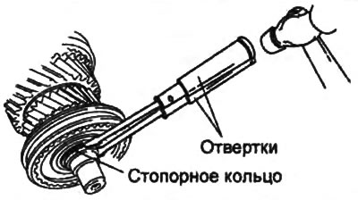

Note: Do not reuse the removed snap ring.


b) Hold the synchronizer hub with your hand and, using a plastic hammer to strike the secondary shaft, remove the hub.
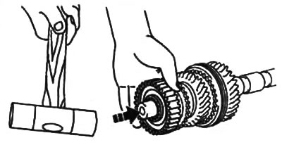
b) Hold the synchronizer hub with your hand and, using a plastic hammer to strike the secondary…


2. Hub of synchronizer of first and second gears.

Using a press, remove the bearing, first gear driven gear, synchronizer assembly and second gear driven gear from the secondary shaft.

Caution: While performing the procedure, support the secondary shaft with your hand to prevent it from falling.
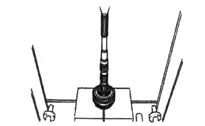

Caution: While performing the procedure, support the secondary shaft with your hand to prevent it…


3. Primary shaft bearing.


Using a press, remove the bearing from the input shaft.
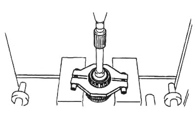
Using a press, remove the bearing from the input shaft.


4. Outer ring of the rear bearing of the intermediate shaft.

Using a press, remove the outer race of the rear bearing from the intermediate shaft.

Caution: While performing this procedure, support the intermediate shaft with your hand to prevent it from falling.
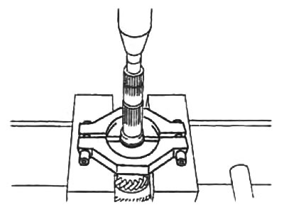

Caution: While performing this procedure, support the intermediate shaft with your hand to prevent…


5. Using a puller, remove the front intermediate shaft bearing.
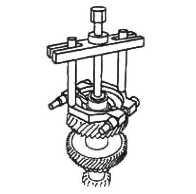
5. Using a puller, remove the front intermediate shaft bearing.


Installation Notes


1. First and second gear synchronizer hub.

a) To assemble the synchronizer, align the grooves on the synchronizer rings with the crackers.

Note: Standard sizes of crackers are shown in the picture.


b) Align the projections on the synchronizer ring with the grooves of the inner conical ring.
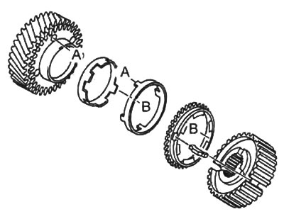
b) Align the projections on the synchronizer ring with the grooves of the inner conical ring.


c) Align the projections of the double cone ring with the holes in the gear.

d) Install the synchronizer hub of the first and second gears on the secondary shaft.

d) Align the mark on the synchronizer hub with the cracker as shown in the figure.
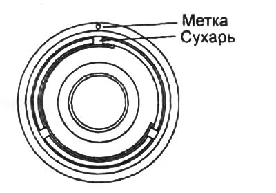
d) Align the mark on the synchronizer hub with the cracker as shown in the figure.


e) Using a press, install the bearing, first gear driven gear, synchronizer assembly and second gear driven gear onto the secondary shaft.

Caution: Be careful when using the press, do not damage the parts.
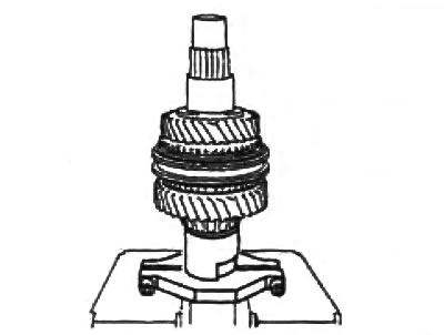


Caution: Be careful when using the press, do not damage the parts.


2. Third and fourth gear synchronizer hub.

a) To assemble the synchronizer, align the grooves on the synchronizer rings with the crackers.

Note: Standard sizes of crackers are shown in the picture.


b) Align the projections on the synchronizer ring with the grooves of the inner conical ring.
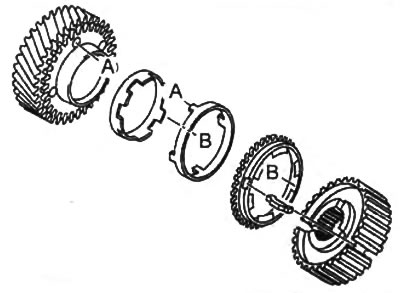
b) Align the projections on the synchronizer ring with the grooves of the inner conical ring.


c) Align the projections of the double cone ring with the holes in the gear.

d) Install the third and fourth gear synchronizer hub onto the secondary shaft.

d) Align the mark on the synchronizer hub with the cracker as shown in the figure.
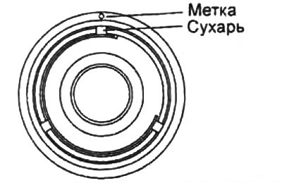
d) Align the mark on the synchronizer hub with the cracker as shown in the figure.


e) Install the spacer and snap ring.


g) Measure the gap between the retaining ring and the spacer.
  • Gap - 0 - 0.05 mm

Gap - 0 - 0.05 mm


If necessary, adjust the thickness of the retaining ring to ensure the specified clearance.

Note: Thrust washers are available in thicknesses from 1.0 mm to 1.90 mm in 0.00 mm increments.


3. Primary shaft bearing.

Using mandrels and a press, install the bearing onto the gearbox input shaft.
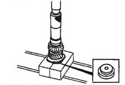
Using mandrels and a press, install the bearing onto the gearbox input shaft.


4. Outer ring of the rear bearing of the intermediate shaft.

Using mandrels and a press, install the outer race of the rear bearing onto the intermediate shaft.
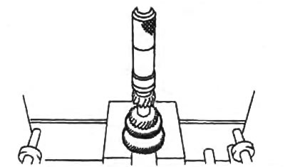
Using mandrels and a press, install the outer race of the rear bearing onto the intermediate shaft.


5. Outer ring of the front bearing of the intermediate shaft.


Using mandrels and a press, install the outer race of the front bearing onto the intermediate shaft.
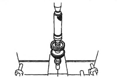
Using mandrels and a press, install the outer race of the front bearing onto the intermediate shaft.
This article is available at: russian, bulgarian, belarusian, ukrainian, serbian, croatian, romanian, polish, slovak, hungarian
This text was checked by: Vladimir Bazhenov
Share with friends on social networks:

Previous
Mazda BT-50 (1) » Mechanical gearbox
Next

Removal and installation gearbox shafts
Fifth gear and reverse gears
Upper cover and crankcase extension
Gearbox assembly — precautions for disassembly and assembly
Gearbox assembly — removal and installation
Gear shift mechanism
Checking gearbox components
More articles on repairing other Mazda models
Disassembling the gearbox shafts Mazda Familia 5 (1985-1989)
Troubleshooting drive shafts Mazda Capella 3 (1982-1992, petrol)
Elimination of gaps in the primary, secondary shafts and differential… Mazda3 BK (2003-2009)
Elimination of gaps in the primary, secondary shafts and differential… Mazda6 GG (2002-2008)
Removal and installation the gearbox oil cooler Mazda CX-5KE (2012-2017)
Link in different formats to this article
Comments and feedback from visitors
No comments yet


How much will 45 + 42 ?


Mazda BT-50 (1) (2006-2011) 
  • General information
  • Introduction to guide
  • User manual
  • Maintenance
  • Power unit
  • Engine repair (diesel)
  • Cooling and lubrication system
  • Fuel injection system
  • Intake and exhaust system
  • Engine electrical equipment
  • Transmission
  • Clutch
  • Mechanical gearbox
  • All-wheel drive system
  • Transfer case and gearboxes
  • Chassis
  • Front suspension
  • Rear suspension
  • Steering
  • Brake system
  • Body
  • Exterior (external elements)
  • Interior (internal elements)
  • Heating and air conditioning
  • Security system SRS
  • Electrical equipment
  • Equipment and devices
  • Electrical circuits
Mazda 121 (3) (1996-2003) 
  • General information
  • User manual
  • Maintenance
  • Power unit
  • Petrol engine 1.3 l
  • Petrol engine 1.25/1.4 l
  • Diesel engine
  • Lubrication system
  • Cooling system
  • Ignition system
  • Supply system
  • Fuel injection (gasoline)
  • Fuel injection (diesel)
  • Exhaust system
  • Transmission
  • Clutch
  • Car gearbox
  • Chassis
  • Front suspension
  • Rear suspension
  • Steering
  • Brake system
  • Wheels and tires
  • Body
  • Exterior (external elements)
  • Interior (internal elements)
  • Doors, windows and locks
  • Heating system
  • Electrical equipment
  • Troubleshooting
  • Equipment and devices
  • Lighting system
  • Power devices
  • Electrical circuits
MazBook.ru © 2018–2026 · Mobile version · Articles and news · Sitemap: EN BG BY UA RS HR RO PL SK HU · Feedback · Site search · Add to bookmarks Familia 5 (BF) · Familia 6 (BG) · Capella 3 (GC) · Capella 3 and 4 (GC) · Capella 4 (GD) · Capella 5 (GE) · Capella 6 (GF) · Mazda3 BK · Mazda6 GG · CX-5KE · Mazda 121 (3) · Mazda BT-50 (1) ·
By continuing to use the site, you agree to the use of cookies 🔐