
Note. The models described in this manual are equipped with an airbag system. Before working in close proximity to shock sensors, steering column or front panel, disconnect the wire from the negative battery terminal, then the wire from the positive battery terminal, then wait at least 3 minutes. Accidental airbag deployment can cause injury (see chapter 12). The airbag wiring harness through the dash and center console is yellow. Do not connect a tester or car system wires to these wires.
Warning. If the car radio installed in your car has an anti-theft code, make sure you have the code to unlock it before disconnecting the battery.
1. Disconnect the wire from the negative battery terminal (see Warning and Caution at the beginning of this paragraph).
Dashboard trim
2. If the vehicle has an adjustable steering column, lower it as far down as possible.
3. Remove the lower trim panel on the driver's side (see below).
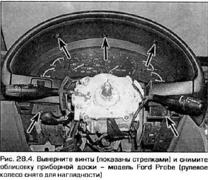
4. On the Ford Probe, remove the five screws securing the instrument panel trim and remove it from the vehicle (pic. 28.4).
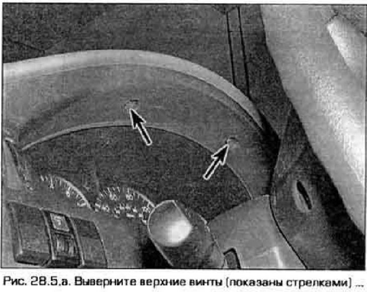
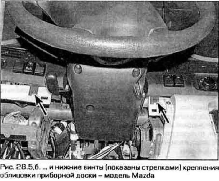
5. On the Mazda model, remove the four screws securing the instrument panel trim (pic. 28.5, a, b). Using a flathead screwdriver, carefully pry up the trim and remove it from the instrument panel, disengaging it from the clips. Be careful not to scratch the front panel.
6. Installation is carried out in sequence. reverse withdrawal. Before installing the cladding, check that all fasteners are in place.
Bottom trim panel
7. Remove the front section of the center console (see paragraph 27).
8. Remove the hood latch handle (see paragraph 11).
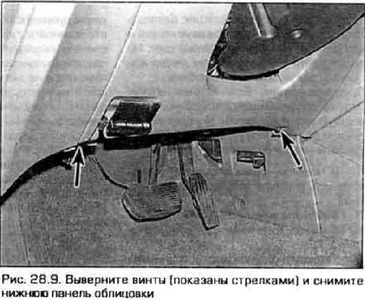
9. Remove the two screws located on the lower edge of the cladding, then disconnect the cladding from the retainers (pic. 28.9).
10. Installation is done in sequence. reverse withdrawal.
Central section of front panel
11. Remove the center console (see paragraph 27).
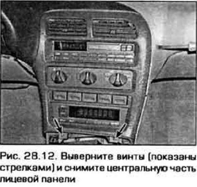
12. Remove the screws along the bottom edge of the panel, then pull on the panel to disengage it from the clips and from the dashboard (pic. 28.12).
13. Installation is made in sequence, return to removal.
Glove box
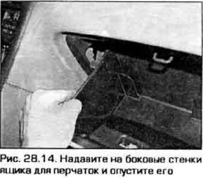
14. Open the glovebox lid, squeeze the sides of the lid and lower it (for access to fixing screws) (pic. 28.14).
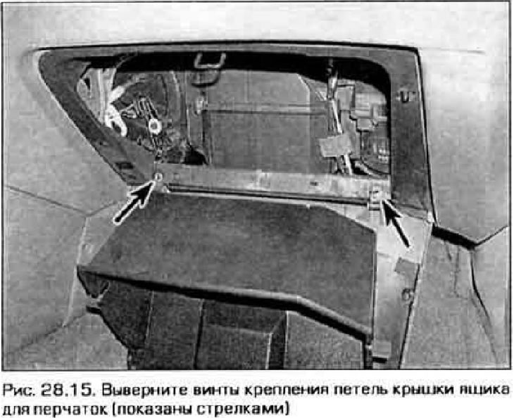
15. Remove the screws and remove the glove box from the front panel (pic. 28.15).
16. Installation is made in sequence, return to removal.