
Diagram of the EEC-V engine management system
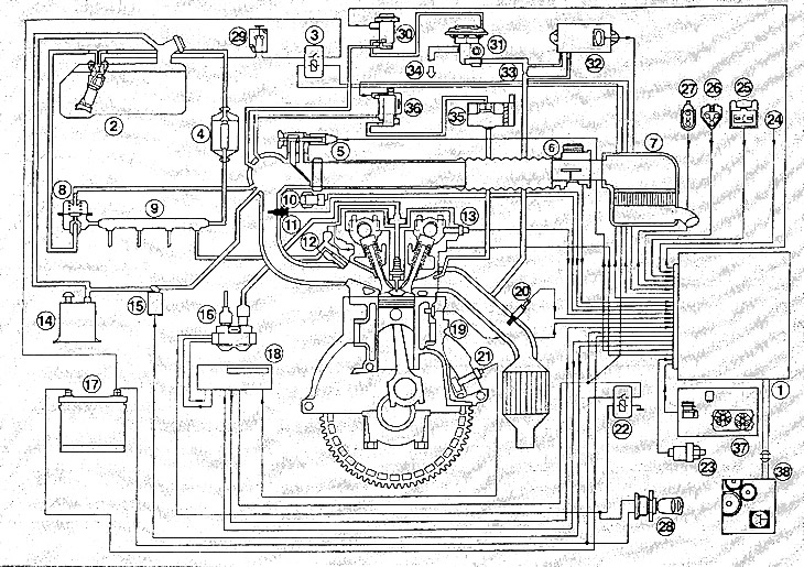
1. EEC-V module; 2. Fuel pump; 3. Fuel pump relay; 4. Fuel filter; 3. Idle mode control valve; 6. Air flow meter; 7. Air filter; 8. Fuel pressure regulator; 9. Fuel distributor pipe; 10. Throttle position sensor; 11. Inlet air temperature sensor; 12. Nozzle; 13. Camshaft position sensor; 14. Capacity (storage device) with activated carbon; 15. Cleaning solenoid valve; 16. Ignition coil; 17. Rechargeable battery; 19. Coolant temperature sensor; 20. Lambda probe (oxygen sensor); 21. Crankshaft speed sensor; 22. Power relay; 23. Power steering pressure switch; 24. Air conditioning compressor clutch; 27. Diagnostic plug for diagnostic tool; 28. Fuel switch; 30. Electronic vacuum regulator; 31. Exhaust gas recirculation valve; 32. Pressure difference converter; 34. To the intake manifold; 37. Switching off the air conditioner/radiator fan; 38. Automatic transmission control.
Note: Only parts that are installed in the vehicle are listed here.
The ignition and fuel injection systems are controlled by the engine management system, designated EEC-V. This chapter deals mainly with the injection system.
The advantages of a gasoline injection system compared to a conventional carburetor are as follows:
Precisely metered amount of fuel in each engine operating mode, which ensures low fuel consumption with good engine performance.
Reduced emissions of toxic substances thanks to precise dosing of fuel and catalyst with lambda control.
Self-diagnosis of the injection system and quick fault finding.
The control unit is equipped with an error memory unit. If malfunctions of the ignition and fuel injection systems appear during operation, their codes are stored in the memory block. If the injection system or the engine is not working properly, a workshop can carry out troubleshooting.
Attention: If the wires from the battery are disconnected, the data in the unit is erased.
The injection system consists of reliable parts and practically does not need maintenance, only the air and fuel filters are replaced during maintenance. The necessary adjustment and repair work should only be carried out with the help of complex and expensive measuring instruments, so these robots should be made in a workshop.
Caution: When working on the injection system, the cleanliness requirements for the fuel system must be observed, as well as the safety regulations for working on the ignition system.