


Assembly Notes
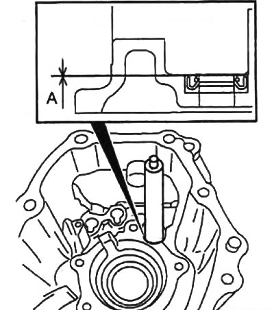
1. Control lever seal.
a) Apply grease to the sealing lip of the oil seal.
b) Using a drift and hammer, install the seal as shown in the figure.
- Installation depth "A" - 0 mm
Note: Do not confuse the position of the oil seal during installation.
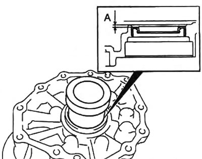
2. Input shaft seal.
a) Apply grease to the sealing lip of the oil seal.
b) Using a drift and hammer, install the seal as shown in the figure.
- Installation depth "A" - 2.4-3.0 mm
3. Input shaft bearing.
a) Using mandrels and a press, install the bearing.
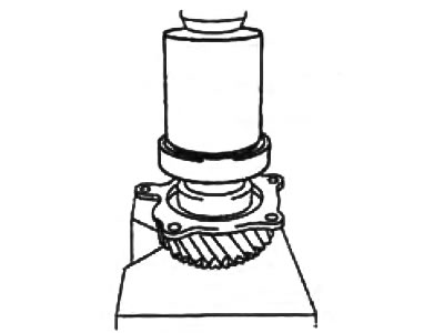
b) Install the retaining ring.
c) Measure the gap shown in the figure.
- Gap - 0 - 0.15 mm
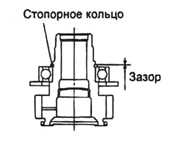
If the gap is not within the norm, adjust the thickness of the retaining ring.
Note: Retaining rings are available in 2.60 thickness; 2.67 and 2.74 mm.
4. Front and rear intermediate shaft bearings.
Using a press and mandrels, install the bearings on the intermediate shaft.
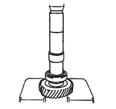
Front bearing.
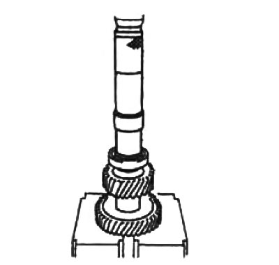
Rear bearing.
5. Intermediate shaft.
a) Install the intermediate shaft into the front housing.
b) Measure the distance "A" shown in the figure.
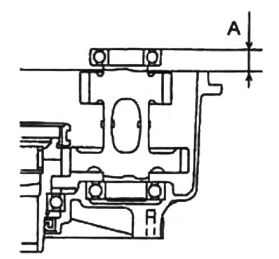
c) Based on the measured distance "A", select the adjusting spacer according to the table.
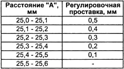
d) Install the adjusting spacer.
6. Front bearing of rear output shaft and rear output shaft.
a) Using a mandrel and press, install the front bearing onto the rear output shaft.
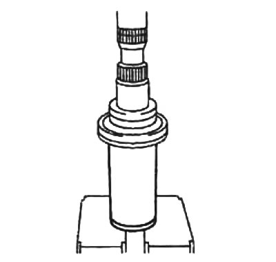
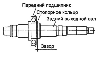
b) Measure the clearance between the snap ring and the groove in the rear output shaft.
- Gap - 0-0.15 mm
c) Install the rear output shaft into the center housing. Tap the shaft into the housing using a plastic hammer.
7. Central building.
a) Apply sealant to the contact surface of the center body as shown in the figure.
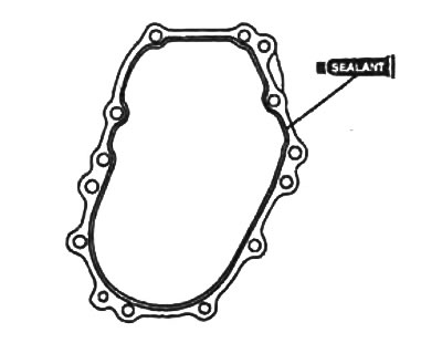
b) Install the central body and tighten the bolts.
- Bolt length - 43 mm
- Tightening torque - 11 - 48 Nm
8. Oil drain.
Install the oil drain on the center housing. When installing, align the grooves.
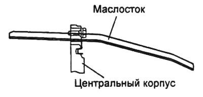
9. Oil catch tank.
a) Align the oil catch can groove.
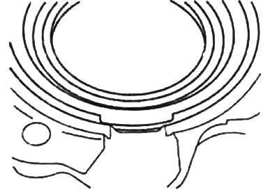
b) Apply oil to the sealing lip.
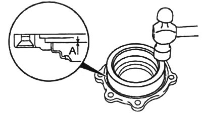
c) Using a drift and hammer, install the oil catch can as shown in the figure.
- Installation depth "A" - 0 mm
10. Chain, front output shaft and drive sprocket.
a) Install the chain, front output shaft and drive sprocket assembly into the housing. Tap the front output shaft into the housing with a plastic hammer.
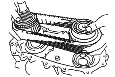
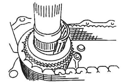
b) Rotate the rear output shaft to install the drive sprocket needle bearing.
11. Front and rear bearings of the front output shaft.
Using drifts and a hammer, install the bearing onto the front output shaft.
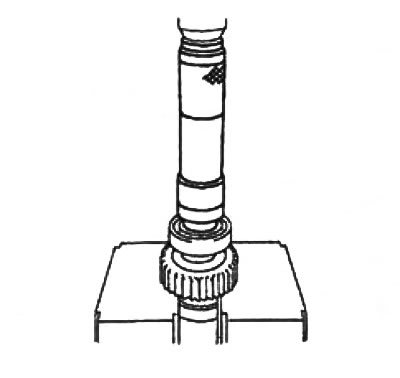
Front bearing.
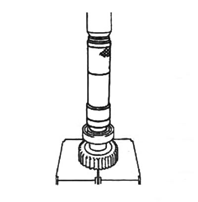
Rear bearing.
12. All-wheel drive engagement hub.
Using drifts and a hammer, install the all-wheel drive engagement hub.
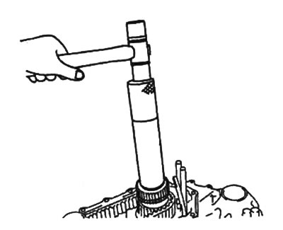
13. Rear bearing of the rear output shaft.
Using drifts and a hammer, install the rear bearing onto the rear output shaft.
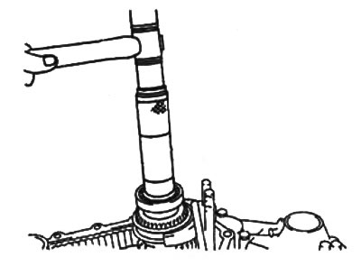
14. Rear body.
a) Apply sealant to the contact surface of the rear housing as shown in the figure.
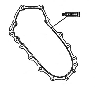
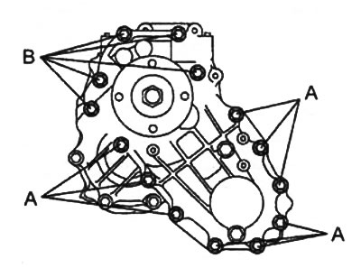
b) Install the rear housing and tighten the bolts.
Bolt length:
- bolts "A" - 58 mm
- bolts "B" - 113 mm
Tightening torque - 41 - 48 Nm
15. Front output shaft seal.
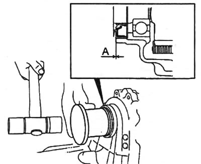
a) Apply grease to the sealing lip of the new oil seal.
b) Using a drift and hammer, install the seal as shown in the figure.
- Installation depth "A" - 0 mm
16. Rear output shaft seal.
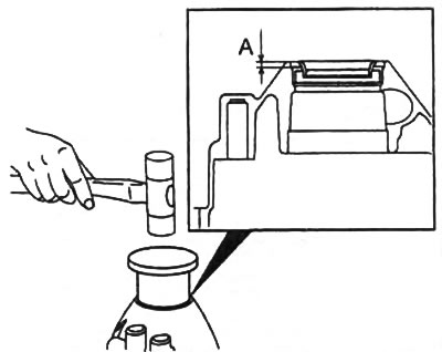
a) Apply grease to the sealing lip of the new oil seal.
b) Using a drift and hammer, install the seal as shown in the figure.
- Installation depth "A" - 6.7 - 7.3 mm
17. Control mechanism cover.
a) Apply sealant to the contact surface of the control mechanism cover as shown in the figure.
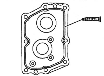
b) Install the cover and tighten the bolts.
- Tightening torque - 16 - 33 Nm