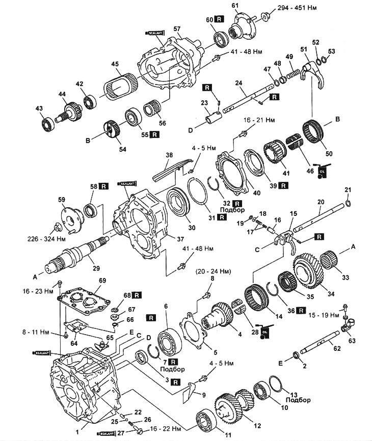
Transfer case.
1 - front body,
2 - control rod gland,
3 - input shaft seal,
4 - shaft,
5 - holder, input bearing
6 - input shaft bearing,
7 - retaining ring,
8 - bolt,
9 - oil deflector,
10 - rear intermediate shaft bearing,
11 - front intermediate shaft bearing,
12 - intermediate shaft,
13 - adjusting spacer,
14 - downshift clutch,
15 - downshift fork,
16 - plunger,
17 - spring,
18 - washer,
19 - retaining ring,
20 - downshift engagement rod,
21 - retaining ring,
22 - locking pin,
23 - a tip of a rod of inclusion of a full drive,
24 - all-wheel drive activation rod,
25 - steel ball,
26 - spring,
27 - locking bolt,
28 - input shaft needle bearing,
29 - rear output shaft,
30 - front bearing of the rear output shaft,
31, 32 - retaining ring,
33 - needle bearing of the drive gear of the reduction gear,
34 - downshift gear,
35 - downshift hub,
36 - retaining ring,
37 - central building,
38 - oil drain,
39 - oil catcher,
40 - holder of the front bearing of the rear output shaft,
41 - leading sprocket,
42 - rear bearing of the front output shaft,
43 - front bearing of the front output shaft,
44 - front output shaft,
45 - chain,
46 - drive sprocket bearing,
47 - retaining ring,
48 - bushing,
49 - spring,
50 - all-wheel drive clutch,
51 - all-wheel drive fork,
52 - spacer,
53 - retaining ring,
54 - all-wheel drive hub,
55 - rear bearing of the rear output shaft,
56 - speedometer drive gear,
57 - rear case,
58 - front output shaft seal,
59 - flange of the front output shaft,
60 - rear output shaft seal,
61 - flange of the rear output shaft,
62 - control rod,
63 - control rod tip,
64 - guide plate,
65 - return lever,
66 - return lever spring,
67 - bushing,
68 - retaining ring,
69 - control mechanism cover.
Note:
- Installation of details is made in an order, the return to removal.
- When assembling, it is necessary to select the dimensions of the parts indicated in the assembly drawing by the inscription "Selection".
Disassembly Notes
1. Front and rear output shaft flanges.
A) While holding the flange, unscrew the nut using the retainer.
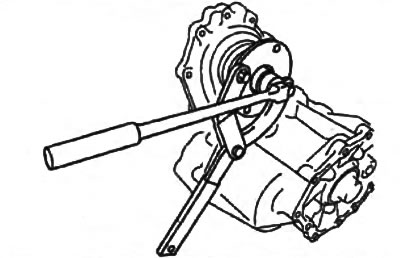
Front output flange.
Flange of the rear output shaft.
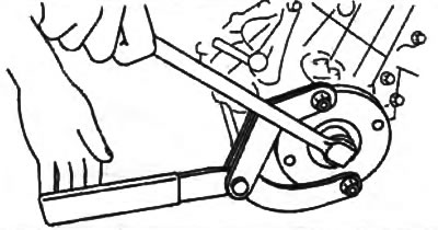
b) Remove the flange using a puller.
Front output flange.
Flange of the rear output shaft.
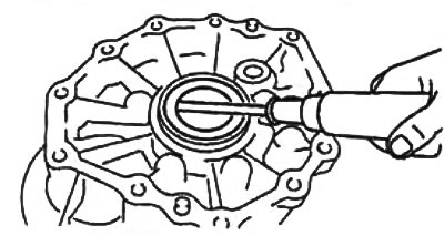
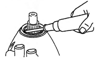
2. Rear output shaft seal. Using a slotted screwdriver, remove the rear output shaft seal.
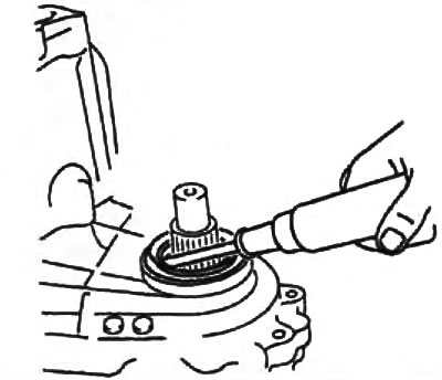
3. Front output shaft seal. Using a slotted screwdriver, remove the front output shaft seal.
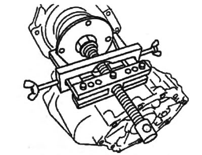
4. Rear bearing of the rear output shaft.
Using a puller, remove the rear bearing from the rear output shaft.
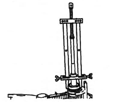
5. All-wheel drive clutch. Using a puller, remove the 4WD clutch from the rear output shaft.
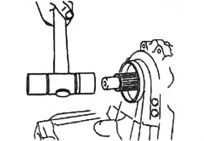
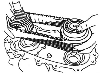
6. Chain, front output shaft and drive sprocket,
A) Using a plastic mallet, tap the front output shaft out of the transfer case housing.
b) Remove the front output shaft, chain and sprocket assembly.
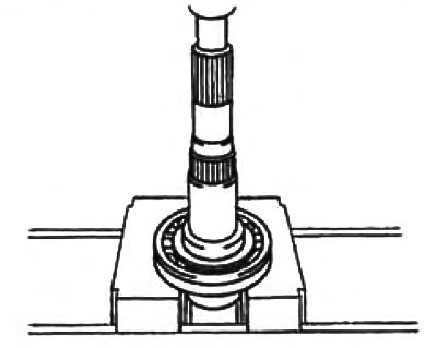
7. Front and rear bearings of the front output shaft.
Using a press, remove the bearing from the front output shaft.
front bearing.
Rear bearing.
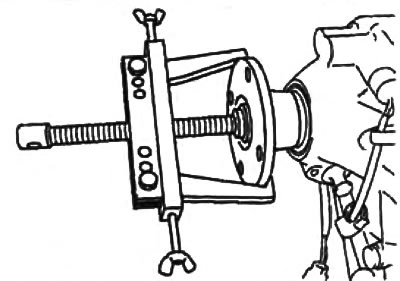
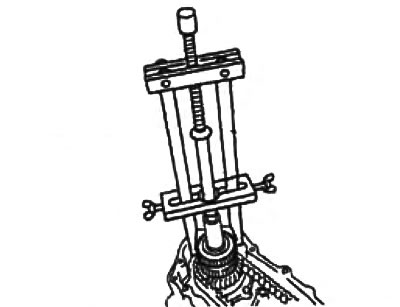
8. Front bearing of the rear output shaft.
Using a puller, remove the front bearing from the rear output shaft.
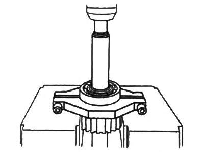
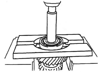
9. Front and rear intermediate shaft bearings.
Using a press, remove the bearing from the intermediate shaft.
front bearing.
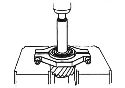
Rear bearing.
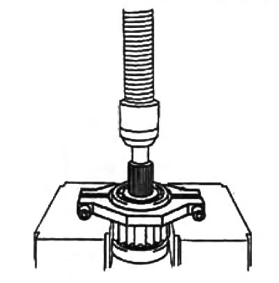
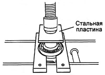
10. Input shaft bearing.
Using a press and a steel plate, remove the bearing from the input shaft.
- Plate thickness - not less than 10 mm
11. Control rod seal.
Using a slotted screwdriver, remove the control rod seal.
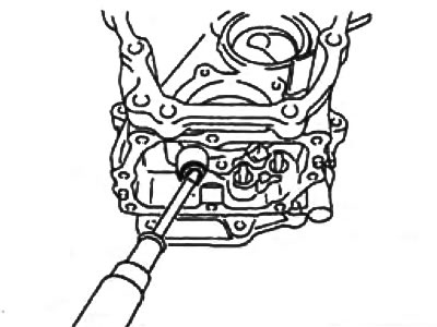
12. Input shaft seal.
Using a slotted screwdriver, remove the input shaft seal.