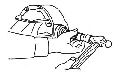
2. Install the final drive driven gear.
a) Apply sealant to the contact surfaces of the driven gear and differential housing.
b) Install the driven gear and tighten the bolts.
- Tightening torque - 69 - 83 Nm
3. Using a press and a mandrel, press the side bearings onto the differential housing.
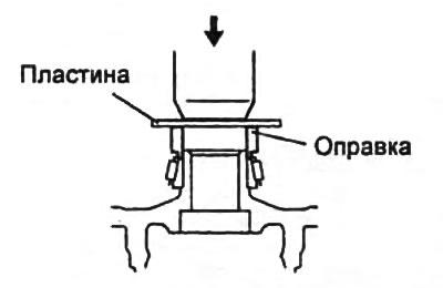
4. Using a press and a mandrel, press the outer race of the front bearing into the gearbox housing.
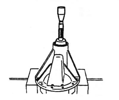
5. Using a press and a special mandrel, press the outer ring of the rear bearing into the gearbox housing.
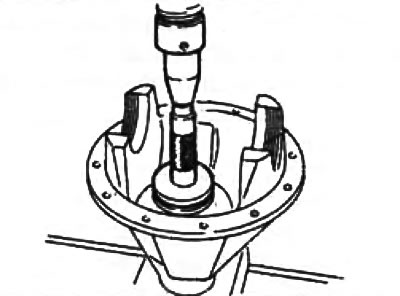
6. Adjusting the height of the drive gear.
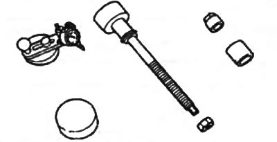
Special devices for adjustment
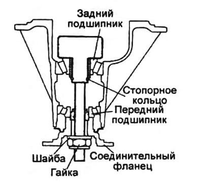
a) Place the rear bearing on the special tool and install the tool together with the rear bearing into the gearbox housing.
b) Install the front bearing and washer using the special tool. Tighten the special tool nut so that it can be rotated by hand.
Caution: Do not install adjusting shims.
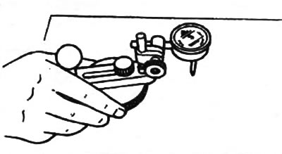
c) Place the special device with the pointer indicator on a flat surface and set the indicator arrow to zero.
d) Install the device with the indicator, as shown in the figure.
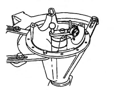
d) Place the indicator measuring tip on the place of the gearbox housing where the side bearing beds are located. Measure the positions of the lowest points of the right and left bearing beds.
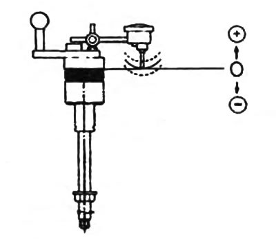
e) Add the quantities (right and left), defined in point "d", and divide the resulting amount by 2.
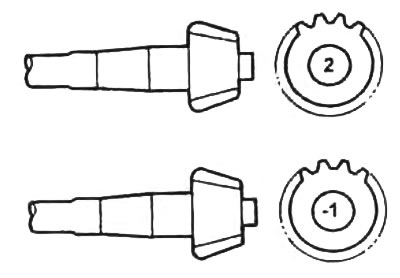
From the result, subtract the number printed on the end of the drive gear and divide by 100 (the absence of a number corresponds to the value zero).
The article is reprinted from the portal: MazBook.ru
Meaning of marks on the drive gear:
- "2" — + 0.02 mm
- "-1" — -0.01 mm
Example:
- The value of the two measured values is 0.18 and 0.26 mm and the number on the drive gear is 2. (0.18 + 0.26)/2 - 2/100 - 0.20. The adjustment index value for this drive gear and gearbox housing set is 0.20 mm.
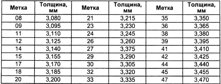
- Select adjusting shims of this thickness and install them between the bearing housing and the gearbox housing.
Note:
- select the thickness of the set of adjusting shims with an accuracy of 0±0.03 mm;
- no more than five pads can be used.
Note: For the correspondence between the spacer thickness and the identification number, see the "Adjusting Spacer Thickness" table.
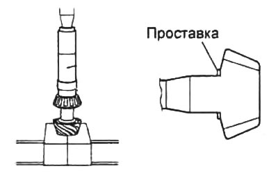
7. Using a press and special mandrels, press the rear bearing onto the drive pinion shaft.
8. Adjusting the preload of the drive gear bearings.
Caution: Do not install the oil seal.
a) Install the pinion gear, new spacer sleeve, coupling flange, washer and new adjusting nut into the bearing housing. Temporarily tighten the adjusting nut.
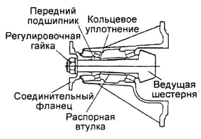
b) To install the bearings, turn the connecting flange by hand.
c) To achieve the set bearing preload, hold the connecting flange with a special device and tighten the adjusting nut to the lower tightening torque value.
- Tightening torque - 128 - 284 Nm
- Preload of pinion bearings - 1.28 - 1.76 Nm
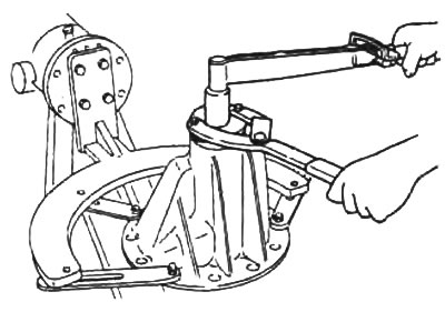
Note: If the specified preload cannot be achieved, disassemble the assembly, re-adjust the pinion height, and adjust the preload using a new spacer sleeve.
d) Remove the adjusting washer and connecting flange.
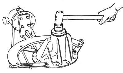
9. Using a drift and hammer, press the seal completely into the housing.
Note: Lubricate the sealing lip of the oil seal with transmission oil.
10. Install the adjusting nuts into the gearbox housing.
Note:
- install the adjusting nuts on the side from which they were removed;
- align the threads on the adjusting nut and the gearbox housing.
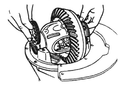
11. Install the bearing caps and temporarily tighten the bolts.
Note: Align the threads on the bearing cap and adjusting nut.
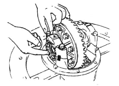
12. Adjusting the backlash.
a) Turning the driven gear of the main transmission, alternately, using a special device, tighten the right and left adjusting nuts to reduce the play.
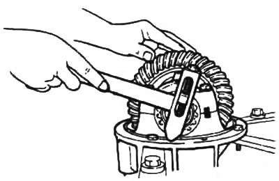
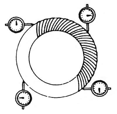
b) Make four marks on the driven gear at 90° intervals.
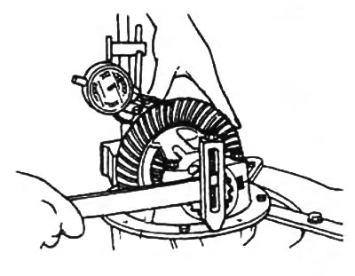
c) Install the pointer indicator on the gearbox housing so that its pin contacts at a direct angle with one of the teeth of the driven gear.
d) While holding the coupling flange, rotate the driven gear to measure the play at the four marked positions.
Make sure that the play in one position corresponds to the established norm, and in other positions does not differ from the measured value by less than 0.07 mm.
Note: The various clearance measurements must fall between the minimum and maximum clearance limits.
- Standard play values are 0.09 - 0.11 mm
- The maximum difference between the clearances is 0.07 mm
Note: To adjust, loosen the adjusting nut on one side and tighten the adjusting nut on the other side by the same amount.
d) If the play value does not fit within the established norms, reduce it by alternately turning both adjusting nuts.
Note: Tighten the adjusting nuts by the same angle if the measured distance between the projections on the bearing caps is less than the standard, and loosen the adjusting nuts if the measured distance exceeds the standard.
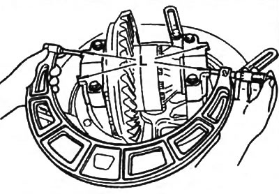
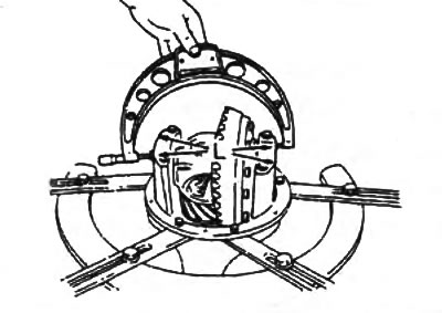
e) Using a micrometer, measure the distance "L" between the projections on the bearing caps as shown in the figure.
- Standard distance "L" - 204.5 mm
 |
 |
g) After adjusting the distance "L", recheck the play.
c) tighten the side bearing cap mounting bolts.
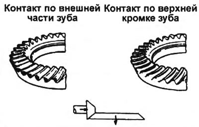
13. Checking and adjusting the contact patch in the main gear.
a) Apply a thin layer of red lead to both surfaces of the 6th - 8th teeth of the driven gear of the main transmission.
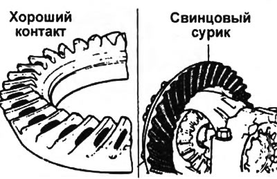
b) Turn the drive gear back and forth several times and check the contact of the teeth.
c) If the contact is good, remove the lead red applied for testing.
d) If the contact is poor, adjust the height of the drive gear and then adjust the backlash.
- Contact along the inside of the tooth and along the base of the tooth.
Select a set of shims to move the drive gear along its axis away from the driven gear.
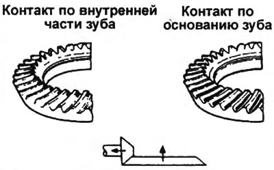
- Contact along the outer part of the tooth and along the upper edge of the tooth.
Select a set of adjusting shims to move the drive gear along the xx axis towards the driven gear.
14. Tighten the bearing cap bolts completely.
- Tightening torque - 73 - 106 Nm
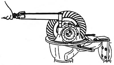
15. Using a drift and hammer, install the side seal.