Assembly notes
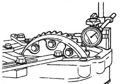
1. Adjust the backlash of the side gears and satellites,
A) Mount the dial indicator on the satellite as shown in the figure.
b) Lock one of the side gears from rotating.
V) By moving the satellite, measure the play.
- Backlash - 0-0.1 mm
If necessary, adjust the play by selecting the thickness of the thrust washers.
2. Install the side gears, thrust washers, pinion gears, pinion shaft and axle pin. Using a rod of suitable diameter, install the pin of the axis of the satellites so that the pin does not protrude from the housing.
3. Install the final drive gear.
A) Apply sealant to the contact surfaces of the driven gear and differential housing.
b) Install the driven gear and tighten the bolts.
- Tightening torque - 130 - 100 Nm
4. Using a press and a mandrel, press the side bearings onto the differential housing.
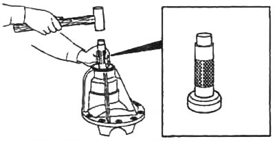
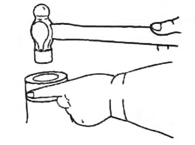
5. Using a hammer and mandrel, install the oil deflector.
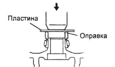
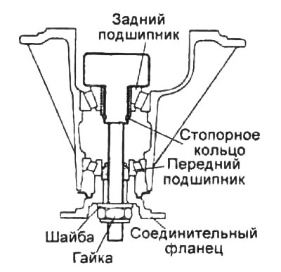
6. Using a press and drift, press the front bearing outer race into the gear housing.
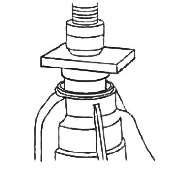
7. Using a press and special drift, press the rear bearing outer race into the gear housing.
8. Pinion height adjustment.
Adjustment tools
A) Slide the rear bearing onto the special tool and install the tool with the rear bearing into the gearbox housing.
b) Install the front bearing and washer onto the special tool. Tighten the tool nut until it can be rotated by hand.
Attention: Do not install shims.
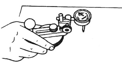
V) Lay the special tool with a dial indicator on a flat surface and set the indicator needle to zero.
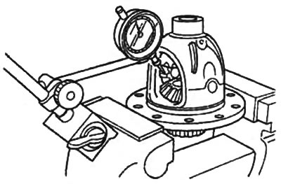
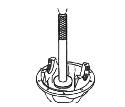
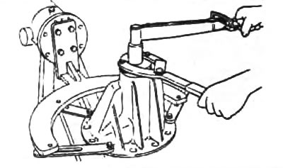
G) Install the indicator tool as shown in the illustration.
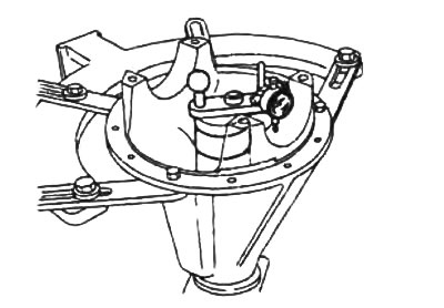
d) Install the measuring tip of the indicator on the place of the gearbox housing where the beds of the side bearings are located. Measure the positions of the lowest points of the beds of the right and left bearings.
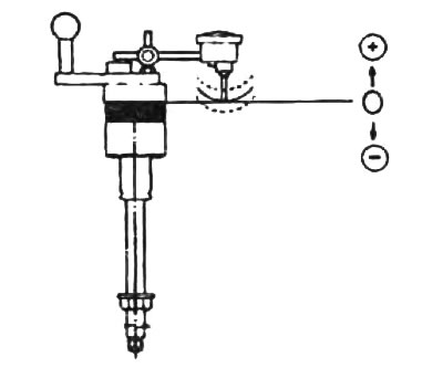
e) Add two quantities (right and left), defined in paragraph "d", and divide the resulting amount by 2.
From the result, subtract the number printed on the end of the drive gear and divided by 100 (the absence of a number corresponds to the value zero).
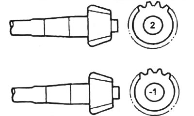
The meaning of the marks on the drive gear:
- "2" - +0.02 mm
- "-1" — - 0.01 mm
Example:
The value of the two measured values is 0.14 and 0.26 mm and the number on the drive gear is 2.
(0,18 + 0,26) /2 - 2/100 = 0,20
The adjustment index value for this pinion and gear case set is 0.20mm.
Choose shims of this thickness and install them between the bearing housing and the gearbox housing.
Note:
- select the thickness of the set of shims with an accuracy of 0±0.03 mm;
- no more than five pads can be used.
9. Using a press and special mandrels, press the rear bearing onto the pinion shaft.

10. Adjusting the preload of the pinion bearings.
Attention: do not install the oil seal.
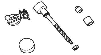
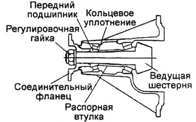
A) Install pinion, new spacer, connecting flange, washer, and new adjusting nut into bearing housing. Temporarily tighten the adjusting nut.
b) To install the bearings, turn the connecting flange by hand.
V) To achieve the set bearing preload, while holding the connecting flange with a special tool, tighten the adjusting nut to the lower torque value.
- Tightening torque - 298 - 500 Nm
- Pinion bearing preload 2.55 - 4.00 Nm
Note: If the preload cannot be achieved, disassemble the assembly, re-adjust the pinion height, and re-adjust the preload with a new spacer.
G) Remove the adjusting nut, washer and connecting flange.
11. Using a drift and a hammer, fully press the gland into the body.
Note: Lubricate the sealing lip of the oil seal with gear oil.
12. Install differential and adjust gear play.
A) Install the differential into the gearbox housing.
b) Push the differential housing towards the left side of the gear housing. Measure the distance between the side bearing and the gearbox housing. The measured distance is the total thickness of the side spacers.
V) Distribute the total thickness of the gaskets obtained in paragraph "b", evenly between the left and right side and install the appropriate spacers. Install the side bearing caps.
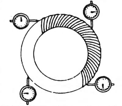
G) Place four marks on the driven gear at 90°intervals.
d) Mount the dial indicator on the gearbox housing so that its pin contacts at a right angle with one of the teeth of the driven gear.
e) While holding the connecting flange, rotate the driven gear to measure the backlash in the four marked positions. Make sure that the minimum amount of play is at least 0.05 mm, and in other positions does not differ from the measured value by less than 0.03 mm.
Note: The various backlash measurements must fall between the minimum and maximum backlash limits.
- Standard backlash values - 0.12 - 0.20 mm
- The maximum difference between backlashes is 0.03 mm
If the backlash value does not fit within the established norms, adjust it by reducing the thickness of the gaskets on one side of the differential and increasing on the other by the same amount.
and) Rotate the drive gear 3 times with a torque wrench and then measure the resistance to rotation.
- Torque less than - 2.4 Nm
If the play is correct, but the resistance to rotation of the pinion exceeds the norm, then adjust the resistance to rotation by reducing the thickness of the side bearing shims.
Note: the thickness of the spacers should be reduced by the same amount on both sides.
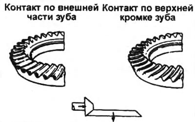
13. Checking and adjusting the contact patch in the final drive.
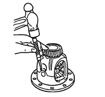
A) Apply a thin coat of red lead to both surfaces of the 6-8 teeth of the final drive gear.
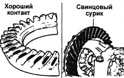
b) Rotate the drive gear back and forth several times and check the contact of the teeth.
V) If the contact is good, remove the red lead applied for testing.
G) If the contact is poor, adjust the pinion height and then adjust the play.
Contact along the inside of the tooth and along the base of the tooth.
Select a set of shims so as to move the drive gear along its axis from the driven gear.
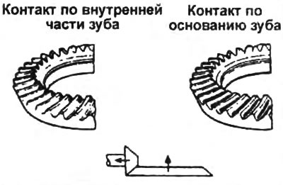
Contact along the outer part of the tooth and along the upper edge of the tooth.
Select a set of shims so as to move the drive gear along its axis to the driven gear.