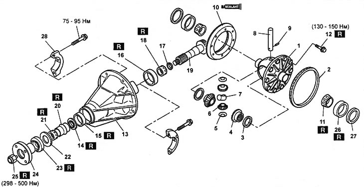
Rear axle reducer (without limited slip differential).
1 - differential case,
2 - speed sensor rotor (models with ABS),
3 - thrust washer,
4 - side gear,
5 - thrust washer,
6 - satellite,
7 - thrust block,
8 - axis of satellites,
9 - pin,
10 - driven gear of the main gear,
11 - side bearing,
12 - bolt,
13 - gearbox housing,
14 - oil deflector,
15 - outer ring of the front bearing,
16 - outer ring of the rear bearing,
17 - adjusting gasket,
18 - rear bearing,
19 - main gear drive gear,
20 - spacer sleeve,
21 - front bearing,
22 - thrust washer,
23 - stuffing box,
24 - flange,
25 - nut,
26 - outer ring of the side bearing,
27 - adjusting gasket,
28 - side bearing cover.
Note: Installation is in the reverse order of removal.
Disassembly Notes
Attention: in order not to damage the parts, install special protective pads on the vise jaws.
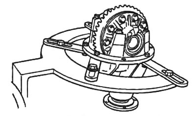
1. Install the gearbox assembly on a special stand.
2. Mark the location of the bearing caps in the gearbox housing.
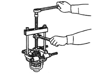
3. Using a special puller, remove the side bearings from the differential case.
Note: Mark right and left bearings.
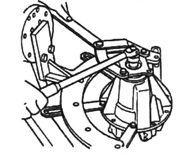
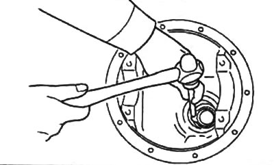
4. Holding the connecting flange with a special tool, unscrew the pinion nut.
5. Using a puller, remove the drive gear coupling flange.
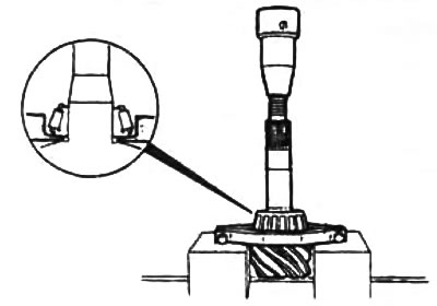
6. Use a plastic mallet to tap the pinion gear out of the gearbox housing.
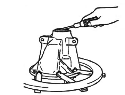
7. Using a slotted screwdriver, remove the gland.
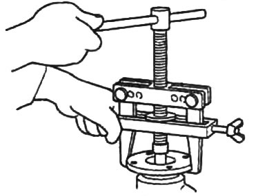
8. Using the tool, remove the drive gear rear bearing.
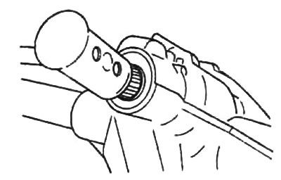
9. Using a copper rod and a hammer, remove the bearing outer race from the gearbox housing.
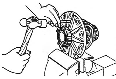
10. Using a copper rod and a hammer, knock out the pin of the satellite axis.
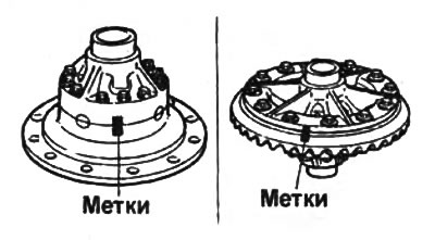
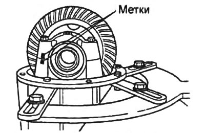
11. Before removal, apply alignment marks to the final drive driven gear, differential housing and differential cups.