
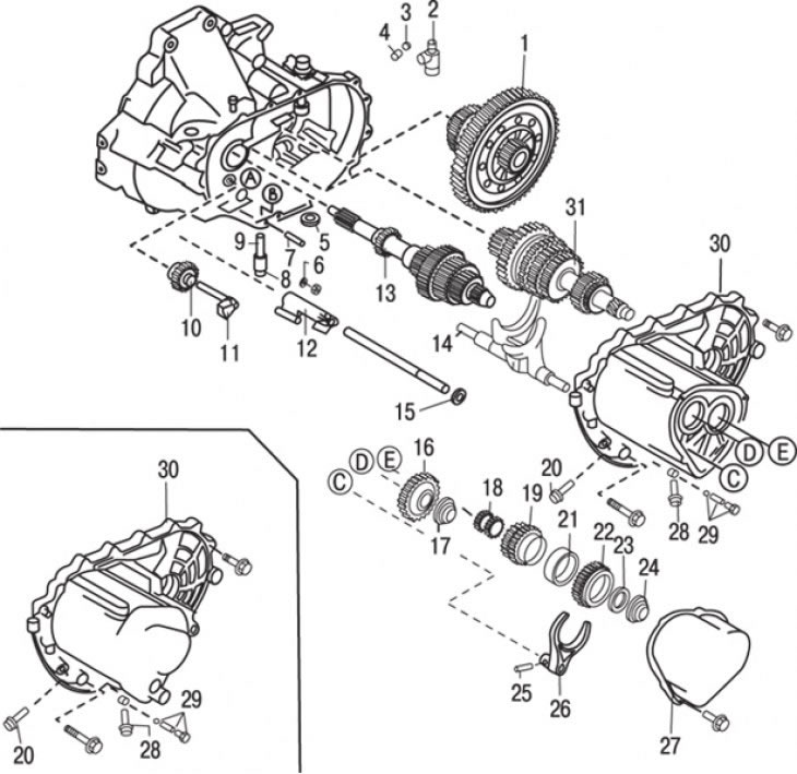
Pic. 9.17. The main elements of the gearbox: 1 - main gear and differential; 2 – knot of the cranked lever; 3 - steel ball; 4 - spring; 5 – magnet; 6 - locking bolt; 7 - spring pin; 8 - ring seal; 9 - crankshaft; 10 – an intermediate gear wheel of a backing; 11 – a shaft of an intermediate gear wheel of a backing; 12 - damper; 13 - node of the input shaft; 14 - shift fork and gear shift rod assembly; 15 - gearshift rods (5th gear and reverse gear) and brace; 16 - gear wheel of the 5th gear; 17 - locknut (5th gear); 18 - gear bushing (5th gear); 19 - gear wheel of the 5th gear; 20 - locking bolt; 21 – a ring of the synchronizer of 5th transfer; 22 – a nave of the synchronizer of 5th transfer; 23 - limiter plate (5th gear); 24 - locknut (5th gear); 25 - spring pin (5th gear); 26 - switch fork (5th gear); 27 - rear crankcase (5th gear); 28 - guide bolt; 29 - locking bolt with ball and spring; 30 - gearbox housing; 31 - secondary shaft assembly
Loosen the bolts and remove the rear crankcase (5th gear) (pic. 9.17).
Using a hammer and chisel, pry back the tabs on each of the locknuts (5th gear).
Carefully block the gears from turning by inserting a screwdriver or similar tool between the teeth of the gears; unscrew the locknuts.
Remove the 5th shift fork locating pin and shift fork.
Remove the 5th limiter plate, hub, synchronizer ring, gear bushing and gear.
Remove the retaining bolt from the gearbox housing.
Remove the guide bolt from the crankcase. Turn out a lock bolt and remove a ball and a spring.
Unscrew the reverse light switch from the gearbox housing.
Mark the position of the electrical wiring clamps to facilitate subsequent assembly and remove the bolts connecting the gearbox housings.
Carefully separate the gearbox housing halves from the clutch housing.
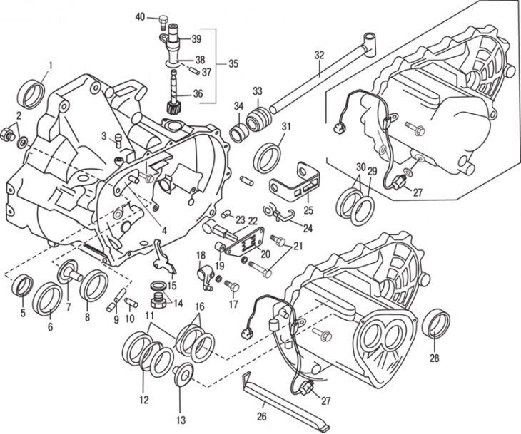
Pic. 9.18. Gearbox housings and elements of the gearshift mechanism: 1 – an epiploon of a power shaft; 2 - bolt and washer; 3 - breather; 4 - breather casing; 5 - seal; 6, 8, 30, 31 - outer rings of bearings; 7, 13 - funnels; 9 – a shaft of the lever of a backing; 10 - spring pin; 11 - the outer ring of the bearing; 12 - diaphragm spring; 14 - drain plug and washer; 15 - reverse gear lever; 16 - adjusting gasket; 17 - bolt; 18 – switching lever; 19 - tube; 20 - guide plates; 21 - bolts; 22 - 5th gear selection lever; 23 - spring pin; 24 - spring; 25 - check valve (5th gear); 26 - oil supply channel; 27 - reverse light switch; 28 - stuffing box; 29 - adjusting gasket; 32 - switching rod; 33 - cover; 34 - stuffing box; 35 - speedometer drive gear assembly; 36 - driven gear; 37 - spring pin; 38 - ring seal; 39 - gear casing; 40 - bolt
Remove the oil supply channel to the 5th gear (pic. 9.18).
Remove the magnet from the gearbox housing.
Remove the countershaft and reverse gear.
Turn out a lock bolt of 5th transfer and a lock plate.
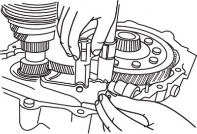
Pic. 9.19. Removing the 4th shift gate and reverse gear lever assembly
On 4-speed models, remove shift gate and reverse gear lever assembly with shifter in neutral position (pic. 9.19).
Remove the 5th gear and reverse gear shaft.
Remove the shift gate for 5th gear and reverse gear.
Knock out the locating pin of the crank arm and remove the 5th gear pin.
Moving the shift rod (5th gear), remove the crank arm assembly.
After making sure that the end surface of the locking sleeve is flush with the end surface of the adjusting lever, turn the selector rod counterclockwise as far as possible.
Lift the selector rod out of the socket, it may be necessary to lift the blocking ball up.
Knock out the dowel pin from the shift rod.
Engage 4th gear by moving the top shift fork up.
Carefully pull the shift rod out of the transmission case. If the link is released from the crankcase, the steel ball will fall off the reverse lever shaft.
Lifting, remove the output shaft with gears and the shift fork assembly from the gearbox housing.
Remove the input shaft assembly.
Remove the differential assembly.
Remove the neutral position switch or 5th gear switch.
Remove the input shaft seals and bearing races.
Remove the funnel from the gearbox housing.
Loosen the bolt and remove the switch guide plate and lever.
Drive out the shift lever locating pin, making sure the shift lever is in the middle position.
Remove the shift shaft cover from the gearbox housing and remove the shaft.
Remove the reverse gear spring pin and selector.
Carefully knock out the bearing races.
Remove the shift rod seal from the transmission case.
Remove the drive axle seal from the gearbox housing by knocking it out with a hammer and punch.
Remove the differential bearing race.
Remove the breather deflector.
Remove the adjusting lever spring.
Output shaft
Remove the output shaft from the gearbox housing.
Clamp the shaft in a vise over two pieces of wood to protect it from damage. Check the axial play of the gears with a feeler gauge.
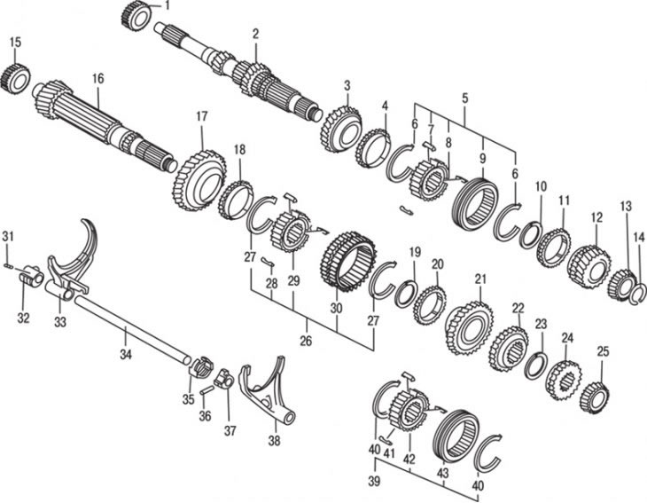
Pic. 9.20. Details of primary and secondary shafts: 1 - the inner ring of the bearing; 2 - input shaft; 3 – a gear wheel of the 3rd transfer; 4 – a ring of the synchronizer of 4th transfer; 5 - synchronizer of 3rd and 4th gears; 6 - retaining ring; 7 - retainer cracker; 8 - synchronizer hub; 9 - sliding clutch of the synchronizer; 10 - retaining ring; 11 - synchronizer ring; 12 - gear wheel of the 4th gear; 13 - the inner ring of the bearing; 14 - thrust ring; 15 - the inner ring of the bearing; 16 - secondary shaft; 17 - gear wheel of the 1st gear; 18 - synchronizer ring; 19 - retaining ring; 20 - synchronizer ring; 21 - gear wheel of the 2nd gear; 22 - gear wheel of the 3rd gear; 23 - retaining ring; 24 - gear wheel of the 4th gear; 25 - the outer ring of the bearing; 26 - synchronizer; 27 - retaining ring; 28 - retainer cracker; 29 - synchronizer hub; 30 - sliding clutch of the synchronizer; 31 - spring pin; 32 - control lever; 33 – a fork of switching of 1st and 2nd transfers; 34 - control rod; 35 - lock sleeve; 36 - spring pin; 37 - control lever; 38 - shift fork of 3rd and 4th gears; 39 - synchronizer; 40 - retaining ring; 41 - retainer cracker; 42 - synchronizer hub; 43 - sliding clutch of the synchronizer
With a bearing puller, remove the 4th gear from the shaft (pic. 9.20).
Remove the synchronizer ring.
Remove the 3rd and 4th gear synchronizer hub circlips.
Carefully remove the 3rd and 4th gear synchronizer hub from the shaft.
Remove the 3rd gear synchronizer ring.
Remove the 3rd gear assembly.
Remove the retaining ring of the thrust washers, then the thrust washers.
Remove the 2nd gear.
Remove the synchronizer ring.
Remove the 1st gear snap ring.
Special tools are required to press out the 1st gear and the 1st and 2nd gear synchronizer. This operation must be performed by a specialist.
Remove the bearing with a puller.
Inspect the gears for wear and damage to the synchronizer cones, hub bushings, teeth and running surfaces.
Check the output shaft for wear and damage to the sliding surfaces, splines and teeth, as well as possible blockage of the lubrication channels.
Check the synchronizer rings by putting them back in place and rotating them to check that they slide smoothly. Use a feeler gauge to measure the gap and compare it with the specifications.
Inspect the synchronizer hub and derailleur for grooves, wear spots, and wear.
Disassemble the synchronizer hub and inspect the splines and surfaces for wear, inspect the springs to make sure they are not bent or loose.
Assemble the hub with the retainer keys raised towards the outside of the hub. When installing the spring, make sure that it is in the center of the biscuit recess.
Use a feeler gauge to check the clearance between the synchronizer hub and the gear selector.
Replace any worn or damaged items with new ones.
Install the bearing on the shaft.
Turn the shaft over and install the 1st and 2nd gear synchronizer hubs with the groove on the shift fork pointing down.
Establish persistent rings of knot of 1st and 2nd transfers.
Install the synchronizer ring into the hub, aligning the slots with the pins in the hub.
Install the 2nd gear.
Install the synchronizer ring into the hub, aligning the grooves with the retainers in the hub.
Install the thrust washers retaining ring.
Install the 3rd gear synchronizer gear and ring.
Install the 3rd and 4th gear synchroniser with the groove down and aligning the slots with the pins in the hub. A press may be required during installation.
Install the 3rd and 4th gear snap ring.
Install the 4th synchro ring with the 4th gear.
To press the bearings onto the shaft, take it to the workshop.
Input shaft
Remove the input shaft and secure it in a vise with two pieces of wood to protect it from damage.
Remove the bearings from the input shaft with a puller.
Inspect the shaft and gears for wear and damage to the splines, sliding surfaces and teeth.
Inspect the bearings for wear, play, and pitting of the cam rollers.
Replace all worn parts with new ones.
Press the bearings onto the shaft and install the input shaft into place.
Differential
Remove the differential from the gearbox housing and secure it in a vise through two wooden blocks to protect it from damage.
Turn out bolts and remove a conducted gear wheel of the main transfer. The final drive gear can be riveted so it cannot be removed.
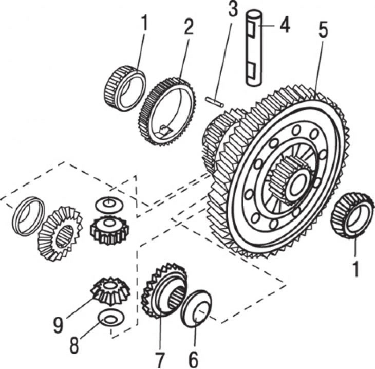
Pic. 9.21. Differential: 1 - inner rings of the bearing; 2 - speedometer drive gear; 3 - spring pin; 4 - the axis of the satellites; 5 - driven gear of the main gear with a differential box; 6, 8 - thrust washers; 7 - side gear; 9 - satellites
Drive the pinion shaft spring pin out of the opposite side of the differential case (pic. 9.21).
Take out an axis of satellites, satellites and persistent washers.
Using a pressing tool, remove the bearing inner race from the differential case.
Remove remaining bearings.
Remove the speedometer drive gear.
Inspect gears, sliding surfaces, and contact surfaces for wear, cracks, and corrosion.
Check the pinion assembly and drive gear. Perform this work with the drive shafts inserted into the differential box. With axles supported on V-blocks, measure the clearance of both gears by manually moving them the full free play distance. If the gap exceeds the allowable, purchase a thrust washer of the appropriate thickness and install it between the differential box and satellites.
Thoroughly wash each part in solvent before assembly.
During assembly, apply clean gear oil to all sliding surfaces and replace with new any spring pins that have been removed.
Install the speedometer drive gear.
Install the bearings using special tools and a hydraulic press, or take the differential to a fully equipped workshop to do the job.
Install the pinion gear and side drives using the appropriate thrust washers.
Install the pinion shaft, making sure the spring pin hole is aligned with the hole in the gearbox.
Install the spring pin with a hammer and punch, working from the side of the speedometer drive gear.
Install the final drive gear and secure with bolts.
Install the differential box to the gearbox housing.