
MazBook.ru
English Русский
Български
Беларускі
Український
Српски
Hrvatski
Română
Polski
Slovenský
Magyar
• Bookmark • Sitemap • Contacts •   
Cars Opel Cars Ford Cars Volkswagen Cars Audi Cars Kia Cars Renault Cars Peugeot


Familia Capella Mazda3 Mazda6 CX-? Others Articles
Capella 3 (1982-1992, petrol) Capella 3 and 4 (1982-1992) Capella 4 (1987-1992) Capella 5 (1991-1997) Capella 6 (1997-2005, petrol)

Removal and installation the gearbox (Mazda Capella GC)

  • Home
  • Mazda Capella
  • Capella GC (1982-1992)
  • Transmission
  • Mechanical gearbox
  • Removal and installation the gearbox
0
Contents: Removal ⇓ Installation ⇓

Removal


Disconnect the cable from the negative battery terminal.

Disconnect the speedometer drive cable from the transmission, the connector from the reverse light switch and, if the model is equipped, the 5th gear switch.

Remove the clutch cable hanger mounting bolts and disconnect the clutch cable from the clutch release lever.

Remove the ground wire mounting bolt and the wiring harness bracket.

Remove the starter.

There are two basic methods for supporting the weight of the engine during crossmember and transmission removal operations. A special support mount that rests on the suspension mounts or a winch can be used to lift the engine. If a support bracket is used, install it first. If using a winch to lift the engine, remove the hood first to increase the working space.
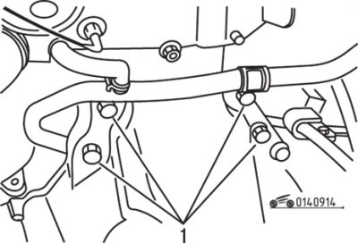
Figure 9.14. Location of the upper bolts (1) securing the gearbox to the engine

Figure 9.14. Location of the upper bolts (1) securing the gearbox to the engine


Remove the four upper transmission-to-engine mounting bolts (figure 9.14).

Raise the front of the vehicle, support it securely on stands, and drain the transmission fluid.

Remove the front wheels, mudguard panels and disconnect the anti-roll bar links. Remove the oil pan guard plate if equipped.


Remove the lower ball joint and steering knuckle mounting bolts, then separate the lower front suspension arms from the steering knuckles.

Separate the left drive shaft from the gearbox.

Remove the intermediate drive shaft. Insert a wooden plug or similar plug to hold the differential axle gears in place.

Separate the shift adjuster rack from the shift rod and separate the extension rod from the gearbox.

Remove the lower gearbox-to-engine mounting bolts.
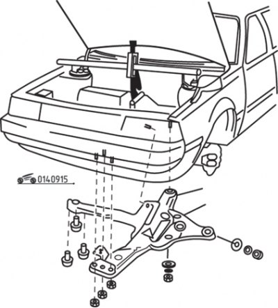
Figure 9.15. Removing the crossmember and lower left arm of the front suspension

Figure 9.15. Removing the crossmember and lower left arm of the front suspension


Loosen the bolt, remove the crossmember and lower the left front suspension arm block (figure 9.15).

Supporting the gearbox with a jack, secure the power unit to the jack.
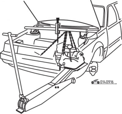
Figure 9.16. Supporting the engine and using an industrial lift to remove the gearbox

Figure 9.16. Supporting the engine and using an industrial lift to remove the gearbox


The original article is available on (www.MAZbook.ru)

Remove the two remaining bolts, separate the gearbox from the engine and lower it down out of the car's engine bay (figure 9.16). Do not allow the gearbox to hang on the input shaft when separating the gearbox from the engine. Secure the transmission in case it falls off the jack.

Installation


Apply a thin coat of Moly lubricant to the gearbox input shaft splines.

Raise the gearbox, attach it to the engine and secure it with bolts, tightening them to the required torque.

Connect the extension rod to the transmission and the shift rod to the shift control rack.

Install the lower control arm assembly and crossmember.

Screw in the lower gearbox mounting bolts.

Install the intermediate drive shaft.

Install the left drive shaft.

Connect the lower ball joints and install the nuts and bolts, tightening them to the specified torque.

Connect the stabilizer bar links.

Install the mudguards and front wheels. Install the oil pan protection plate.

Install the starter.

Remove the jack supporting the transmission and lower the vehicle.

Install the four upper transmission-to-engine mounting bolts. Tighten the bolts to the specified torque.

Install the wire harness clips and ground wire mounting bolt, then connect the clutch cable.

Fill the gearbox housing with oil.

Connect the speedometer drive cable and connectors to the reverse light switch and 5th gear switch.

Connect the cable to the negative terminal of the battery.
This article is available at: russian, bulgarian, belarusian, ukrainian, serbian, croatian, romanian, polish, slovak, hungarian
This text was checked by: Georgy Afanasyev
Share with friends on social networks:

Previous
Capella 3 and 4 » Mechanical gearbox
Next

Gear Shift Lever — removal and installation
Gearbox Mounts — inspection and replacement
Technical data of the manual transmission
General information about manual transmission
Disassembling the gearbox
Gearbox assembly
Replacing gearbox seals
More articles on repairing other Mazda models
Gearbox housing parts Mazda Familia 5 (1985-1989)
Removal and installation the gearbox oil cooler Mazda CX-5KE (2012-2017)
Gearbox/Main gear Mazda 121 (3) (1996-2003)
Link in different formats to this article
Comments and feedback from visitors
No comments yet


How much will 12 + 31 ?


Capella 6 (1997-2005, petrol) 
  • General information
  • Introduction to guide
  • User manual
  • Troubleshooting
  • Maintenance
  • Power unit
  • 4-cylinder engines
  • 6-cylinder engines
  • Engine overhaul
  • Cooling and ventilation
  • Power and exhaust systems
  • Engine electrics
  • Control system
  • Transmission
  • Mechanical gearbox
  • Automatic gearbox
  • Clutch and drive shafts
  • Chassis
  • Brake system
  • Car suspension
  • Steering
  • Body
  • Exterior (external elements)
  • Interior (internal elements)
  • Doors, windows and locks
  • Electrical equipment
  • Equipment and devices
  • Electrical circuits
Capella 5 (1991-1997) 
  • General information
  • User manual
  • Maintenance
  • Helpful hints
  • Power unit
  • Petrol engines 1.6 and 1.8
  • Petrol engines 2.0
  • 2.5 petrol engines
  • Overhaul engines 1.6 and 1.8
  • Overhaul engines 2.0 and 2.5
  • Diesel engine 2.0
  • Engine electrics
  • Cooling system
  • Air conditioner
  • Carburetor Nikki 30/34
  • Power system (1.6 and 1.8)
  • Power system (2.0 and 2.5)
  • Control system
  • Transmission
  • Mechanical gearbox
  • Automatic gearbox
  • Clutch and axles
  • Chassis
  • Brake system
  • Suspension and wheels
  • Steering
  • Body
  • Exterior (external elements)
  • Interior (internal elements)
  • Doors and windows
  • Electrical equipment
  • Equipment and devices
  • Electrical circuits
Capella 4 (1987-1992) 
  • General information
  • Introduction to manual
  • Vehicle specifications
  • Power unit
  • Engine repair
  • Lubrication system
  • Cooling system
  • Fuel system (carburetor)
  • Fuel injection (FE)
  • Fuel injection (DOHC)
  • Fuel system (diesel)
  • Ignition system
  • Transmission
  • Clutch
  • Gearbox
  • Drive shafts
  • Chassis
  • Front suspension
  • Rear suspension
  • Steering system
  • Brake system
  • Electrical equipment
  • Equipment and devices
  • Electrical circuits
Capella 3 and 4 (1982-1992) 
  • General information
  • User manual
  • Maintenance
  • Power unit
  • Gasoline engine
  • Engine overhaul (gasoline)
  • Diesel engine
  • Cooling and heating
  • Supply system
  • Ignition system
  • Emission reduction
  • Transmission
  • Clutch
  • Mechanical gearbox
  • Automatic gearbox
  • Drive shafts
  • Chassis
  • Brake system
  • Suspension and wheels
  • Steering
  • Body
  • Exterior (external elements)
  • Interior (internal elements)
  • Electrical equipment
  • Equipment and devices
  • Power devices
  • Electrical circuits
Capella 3 (1982-1992, petrol) 
  • General information
  • User manual
  • Maintenance
  • Troubleshooting
  • Late models
  • Power unit
  • Engine in car
  • Engine overhaul
  • Cooling and heating system
  • Fuel and exhaust system
  • Engine electrical system
  • Emission control system
  • Transmission
  • Mechanical gearbox
  • Automatic gearbox
  • Clutch and drive shafts
  • Chassis
  • Brake system
  • Suspension and wheels
  • Steering
  • Body
  • Exterior (external elements)
  • Interior (internal elements)
  • Electrical equipment
  • Equipment and devices
  • Lighting and lamps
  • Electrical circuits
MazBook.ru © 2018–2026 · Mobile version · Articles and news · Sitemap: EN BG BY UA RS HR RO PL SK HU · Feedback · Site search · Add to bookmarks Familia 5 (BF) · Familia 6 (BG) · Capella 3 (GC) · Capella 3 and 4 (GC) · Capella 4 (GD) · Capella 5 (GE) · Capella 6 (GF) · Mazda3 BK · Mazda6 GG · CX-5KE · Mazda 121 (3) · Mazda BT-50 (1) ·
By continuing to use the site, you agree to the use of cookies 🔐