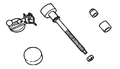
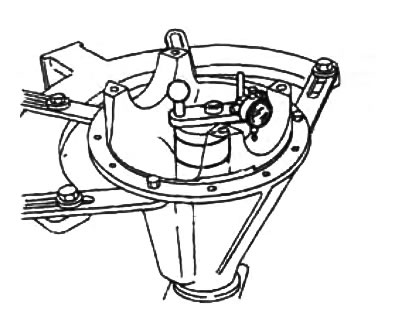
Adjustment tools
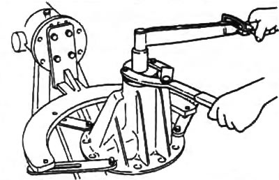
A) Slide the rear bearing onto the special tool and install the tool with the rear bearing into the gearbox housing.
b) Install the front bearing and washer onto the special tool. Tighten the tool nut until it can be rotated by hand.
Attention: Do not install shims.
V) Lay the special tool with a dial indicator on a flat surface and set the indicator needle to zero.
G) Install the indicator tool as shown in the illustration.
d) Install the measuring tip of the indicator on the place of the gearbox housing where the beds of the side bearings are located. Measure the positions of the lowest points of the beds of the right and left bearings.
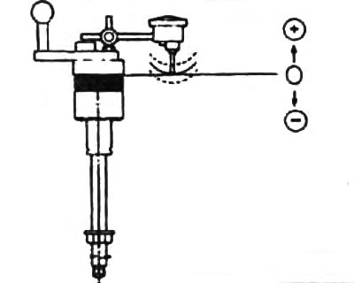
e) Add two quantities (right and left), defined in paragraph "d", and divide the resulting amount by 2.
From the result, subtract the number printed on the end of the drive gear and divided by 100 (the absence of a number corresponds to the value zero).
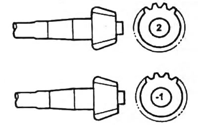
The meaning of the marks on the drive gear:
- "2" - +0.03 mm
- "-1" — -0.03 mm
Example.
The value of the two measured values is 0.14 and 0.26 mm and the number on the drive gear is 2.
(0,18 + 0,26) /2 - 2/100 = 0,20
The adjustment index value for this pinion and gear case set is 0.20mm.
Choose shims of this thickness and install them between the bearing housing and the gearbox housing.
Note:
- select the thickness of the set of shims with an accuracy of 0±0.03 mm;
- no more than five pads can be used.
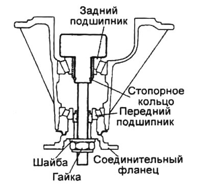
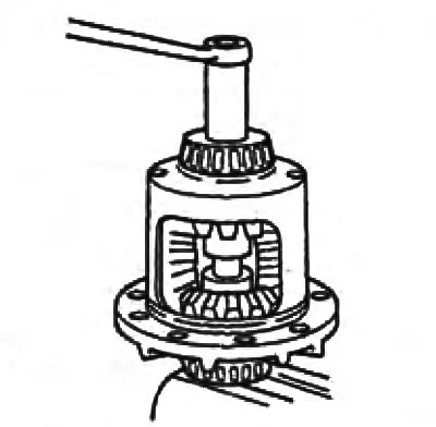
2. Adjusting the preload of the pinion bearings.
Attention: do not install the oil seal.
A) Install the drive gear, new spacer, connecting flange, washer, spacer, front bearing and new adjusting nut into the bearing housing. Temporarily tighten the adjusting nut.
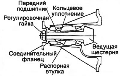
b) To install the bearings, turn the connecting flange by hand.
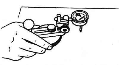
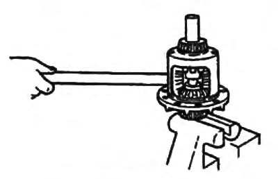
V) To achieve the set bearing preload, while holding the connecting flange with a special tool, tighten the adjusting nut to the lower torque value.
- Tightening torque - 294 - 500 Nm
- Pinion bearing preload 2.55 - 4.00 Nm
Note: If the preload cannot be achieved, disassemble the assembly, re-adjust the pinion height, and re-adjust the preload with a new spacer.
d) Remove the adjusting nut, washer and connecting flange.
3. Assembly of the differential.
Note: Always replace friction discs as a set, even if only one disc is to be replaced.
A) Install the friction discs and circlip on the side gear. Make sure the retaining ring is securely installed.
b) Place the differential housing on a workbench, then install the side gears with friction discs into the differential housing.
V) Install the retainers in the differential housing.
G) Install the differential together with the tools on the axle shaft, aligning the splines.
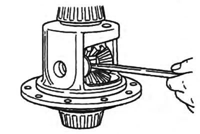
d) Install the pinion gears into the differential case. Hold the satellites with your hand.
e) Tighten the fixture.
and) Using the tool, rotate the differential case and install the satellites.
h) Tighten or loosen the tool until there is little resistance to the rotation of the pinion gears and side gears.
And) By rotating the differential housing, align the holes of both pinion gears with the holes in the differential housing.
To) Tighten tool and install thrust washer.
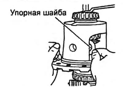
l) Install the thrust washer by pushing it in with a small slotted screwdriver. Align the holes in the washer and differential housing.