


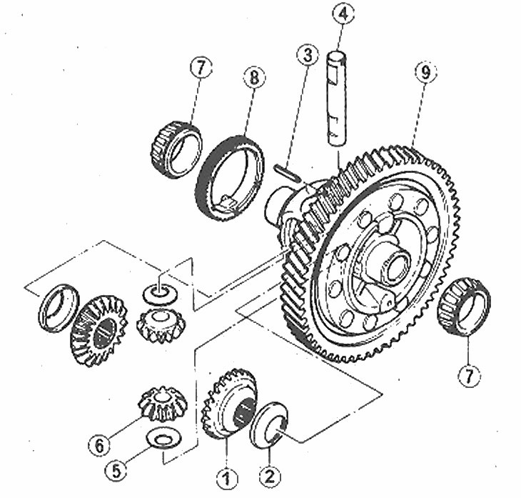
Location of differential assembly components
1. Differential bevel gears; 2. Thrust washer; 3. Spring pin; 4. Axle of satellites; 5. Thrust washer; 6. Satellites; 7. Inner rings of side bearings; 8. Speedometer drive mechanism; 9. Differential driven gear and differential housing assembly
1. Remove the differential (Chapter 5) and clamp it securely in a vice using wooden blocks to protect the surface from damage.
2. Remove the bolts and pull the driven gear out of the differential housing. The driven gear may be riveted to the casing, in which case it cannot be removed.
The original text is published on (Mazbook)
3. Remove the satellite axle spring pin by knocking it out from the opposite side of the casing.
4. Remove the satellite shaft, gears and thrust washers.
5. Remove the inner bearing ring. using a press and a suitable puller.
6. Remove the second bearing using a puller.
7. Remove the speedometer drive mechanism.
8. Inspect gears, friction and contact surfaces for wear, cracks and damage.
9. Inspect the bevel gear and satellite assembly. The inspection is performed without removing the drive shafts from the differential assembly. Support the drive shafts and measure the play of both satellites by manually moving them to the free play distance. If the clearance exceeds the specified value (see Specifications), obtain a thrust washer of the proper thickness from your dealer and install it between the differential housing and the differential bevel gears.
10. Before installation, thoroughly wash each part in solvent.
11. During installation, apply clean transmission oil to all rubbing surfaces and replace all spring pins removed during reassembly with new ones.
12. Install the speedometer drive mechanism.
13. Install the side bearings using a special tool and a hydraulic press, or have this operation performed by your dealer.
14. Install the differential pinions and bevel gears using the appropriate thrust washers.
15. Install the satellite axle so that the hole for the spring pin is aligned with the hole in the casing.
16. Install the spring pin using a hammer and punch, working from the speedometer drive gear side.
17. Install the differential driven gear and tighten the bolts (if applicable).
18. Install the differential assembly into the transmission.