


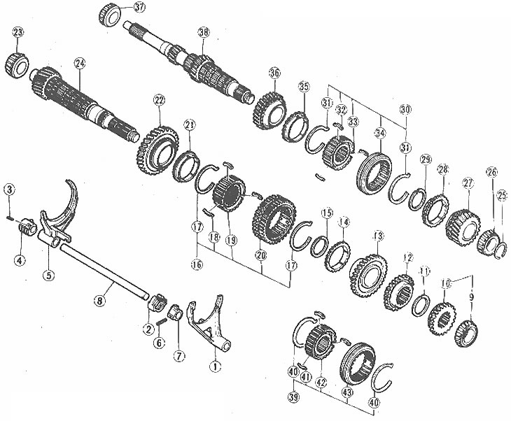
Layout of input and output shaft components
1. Gear shift fork (3rd and 4th gears); 2. Locking sleeve; 3. Spring pin; 4. Tip; 5. Gear shift fork (1st and 2nd gears); 6. Spring pin; 7. Control lever; 8. Gear shift fork rod; 9. Bearing ring; 10. 4th gear; 11. Retaining ring; 12. 3rd gear pinion; 13. 2nd gear; 14. Blocking ring; 15. Retaining ring; 16. Synchronizer; 17. Synchronizer spring; 18. Synchronizer cracker; 19. Synchronizer hub; 20. Reverse gear synchronizer clutch; 21. Synchronizer locking ring; 22. 1st gear pinion; 23. Bearing ring; 24. Output shaft; 25. Thrust ring (4-speed gearbox); 26. Bearing ring; 27. 4th gear; 28. Blocking ring; 29. Retaining ring; 30. Synchronizer of 3rd and 4th gears; 31. Synchronizer spring; 32. Synchronizer cracker; 33. Synchronizer hub; 34. Synchronizer clutch; 35. Synchronizer locking ring; 36. 3rd gear pinion; 37. Bearing ring; 38. Primary shaft; 39. Synchronizer; 40. Synchronizer spring; 41. Synchronizer cracker
1. Remove the assembly and clamp it securely in a vice using wooden blocks to protect the shaft surface.
2. Using a puller, remove the bearings from both ends of the shaft (photo).
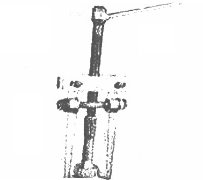
Remove the input shaft bearing using a puller
3. Inspect the shaft and gears for wear and damage to grooves, contact surfaces and teeth.
4. Inspect the bearings for wear and pitting of the support rollers.
5. Replace all worn components with new ones.
6. Place the bearings on the shaft and install the assembly.