


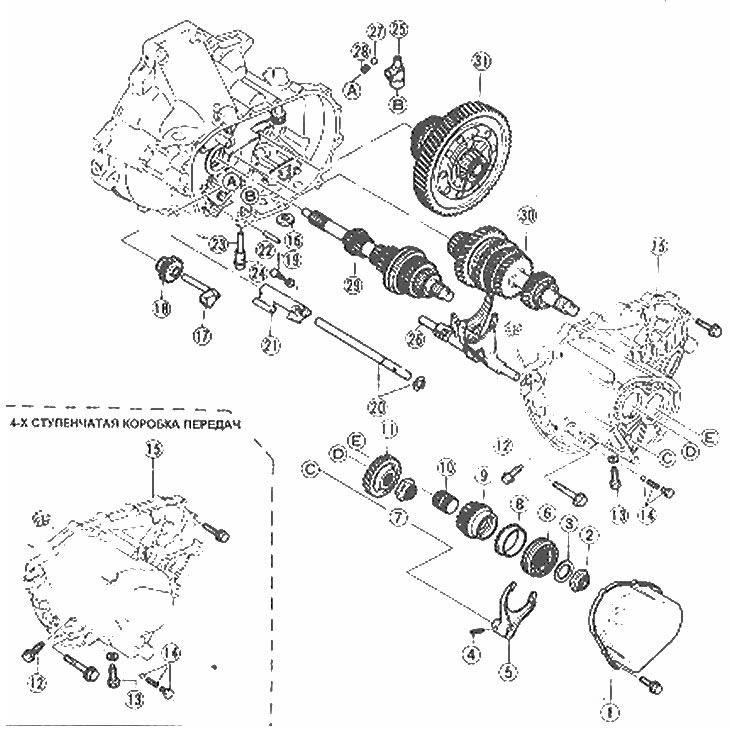
Location of transmission components
1. Back cover (5-speed gearbox); 2. Lock nut (5-speed gearbox); 3. Limiter (5-speed gearbox); 4. Spring pin (5-speed gearbox); 5. Gear shift fork (5-speed gearbox); 6. Synchronizer (5-speed gearbox); 7. Lock nut (5-speed gearbox); 8. Synchronizer locking ring (5-speed gearbox); 9. 5th gear (5-speed gearbox); 10. Gear bushing (5-speed gearbox); 11. Primary gear (5-speed gearbox); 12. Lock bolt; 13. Guide bolt; 14. Lock bolt with spring and ball; 15. Assembling the transmission housing; 16. Magnet; 17. Reverse shaft; 18. Reverse intermediate gear; 19. Lock bolt; 20. Gear shift rod (5th and reverse) and a bracket; 21. Reverse gear selector; 22. Spring pin; 23. Double-arm lever shaft; 24. O-ring seal; 25. Assembling the double-arm lever; 26. Assembling the gear shift forks and rod; 27. Steel ball; 28. Spring; 29. Assembling the primary shaft gears
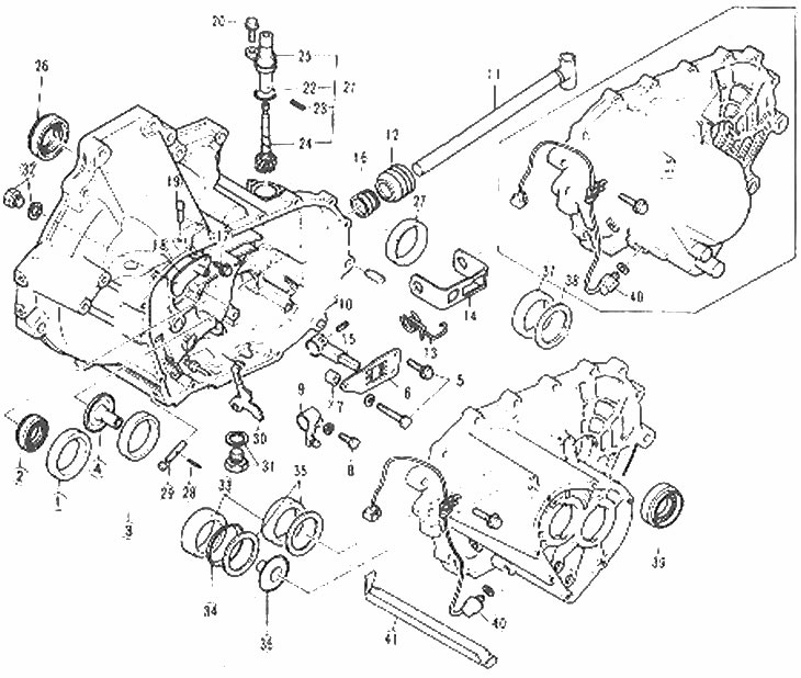
Transmission housing and gear selector mechanism components
1. Bearing outer ring; 2. Seal; 3. Bearing outer ring; 4. Bearing support; 5. Bolts; 6. Guide plate; 7. Bushings; 8. Bolt; 9. Shift lever; 10. Spring pin; 11. Leash roller; 12. Case; 13. Spring (5-speed gearbox); 14. Reverse gear selector (5-speed gearbox); 15. The lever of the leash roller; 16. Seal; 17. Bolts; 18. Breather cap; 19. Sapun; 20. Bolts; 21. Assembling the speedometer drive; 22. O-ring seal; 23. Spring pin; 24. Driven gear; 25. Speedometer drive housing; 26. Input shaft seal; 27. Bearing outer ring; 28. Spring pin; 29. Reverse gear lever shaft; 30. Reverse gear lever; 31. Drain plug and washer; 32. Bolt and washer; 33. Outer bearing ring; 34. Spring washer; 35. Adjusting shim; 36. Bearing support; 37. Bearing outer ring; 38. Adjusting shim; 39. Seal; 40. Reversing light switch; 41. Lubrication channel
1. Unscrew and remove the back cover (5-speed gearbox).
2. Using a punch, remove the locking rims of the lock nuts from the grooves (5-speed gearbox).
3. Carefully lock the gear teeth with a screwdriver or similar tool and remove the lock nuts (photo).
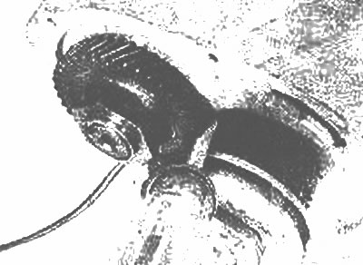
Insert a screwdriver into the gear teeth to lock the shaft |
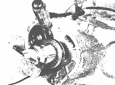
Make sure the screwdriver does not slip when removing the lock nuts |
4. Remove the 5th gear shift fork mounting pin and the fork itself (photo).
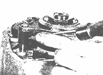
Knock out the shift fork mounting pin using a hammer and punch
5. Remove the 5th gear limiter, the synchronizer assembly, its locking ring, the gear sleeve and the gear itself.
6. Remove the lock bolt from the transmission housing (photo).
Remove the lock bolt
7. Remove the guide bolt from the crankcase (photo). Remove the lock bolt, ball, and spring.
Remove the guide bolt from the crankcase
8. Unscrew the reverse light wiring connector from the crankcase.
9. Mark the location of the wiring harness clamp for ease of installation later and remove the transmission bolts.
10. Carefully separate the crankcase halves (photo).
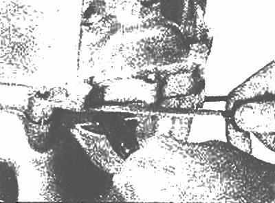
Use two screwdrivers to separate the transmission housing halves |
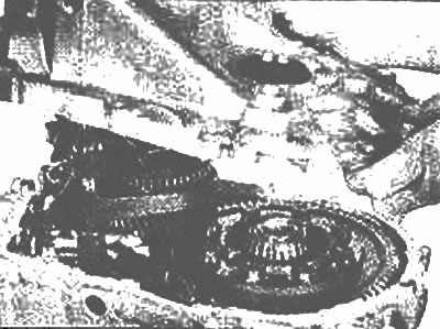
Carefully remove the crankcase half from the shafts |
11. Remove the 5th gear oil channel (photo).
Use a scraper to remove the 5th gear oil channel
12. Remove the magnet from the crankcase.
13. Remove the reverse gear shaft and the gear itself (photo).
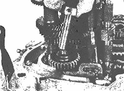
Remove the reverse shaft and gear
14. Remove the 5th gear and reverse gear lock bolt (photo).
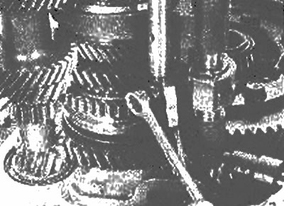
Remove the 5th gear and reverse lock bolt
15. On models with a 4-speed transmission, remove the reverse gear selector and lever assembly, setting the reverse gear shaft lever to the neutral position.
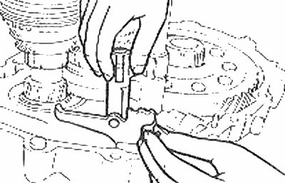
On 4-speed models, remove the reverse gear shift lever assembly (Chapter 5)
16. Remove the 5th gear and reverse gear engagement rod (photo).
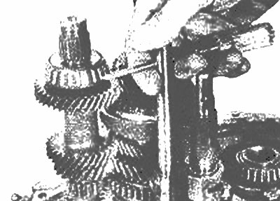
Use a screwdriver to remove the 5th gear and reverse gear selector rod
17. Remove the 5th gear and reverse gear selector (photo).
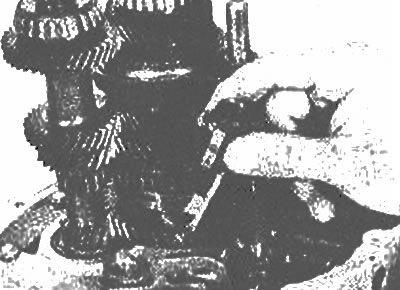
Remove the 5th gear and reverse gear selector lever
18. Knock out the double-arm lever mounting pin and remove the lever axle (5-speed gearbox) (photo).
The article is reprinted from the portal MAZBOOK.RU
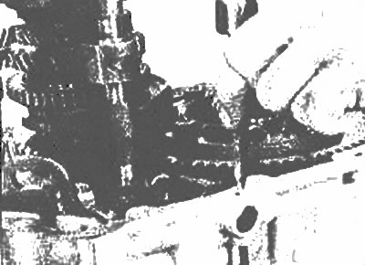
Use a punch to knock out the double-arm lever mounting pin |
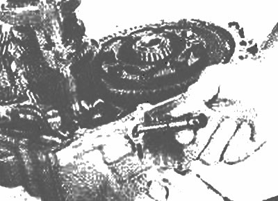
Remove the double-arm lever axle |
19. Remove the double-arm lever assembly by moving the lever shaft to release the lever (5-speed gearbox) (photo).
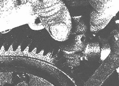
Remove the double-arm lever by moving the gear shift rod
20. After making sure that the end of the locking sleeve is level with the end of the control lever, turn the fork rod counterclockwise until it stops (photo).
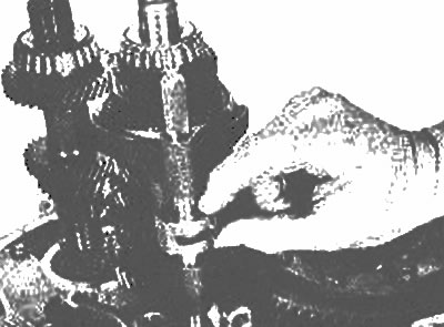
Turn the stem counterclockwise
21. Pull out the gear shift rod. It may be necessary to remove the locking ball.
22. Knock out the mounting pin from the gear shift rod (photo).
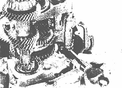
Use a punch to drive the mounting pin out of the rod
23. Set the transmission to 4th gear by moving the upper gear engagement fork up (photo).
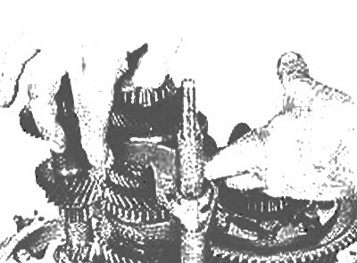
Set the transmission to 4th gear by moving the gear shift fork up
24. Carefully remove the gear shift rod from the crankcase. A steel ball will fall out of the reverse gear lever axis.
25. Remove the output shaft and gear shift fork assembly from the transmission housing (photo).
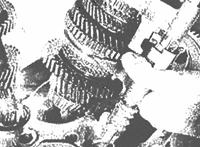
Remove the output shaft assembly
26. Remove the primary gear assembly.
27. Remove the differential assembly (photo).
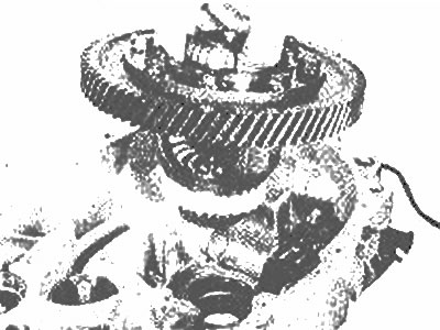
Lift the differential assembly out of the transmission housing
28. Remove the 5th gear select indicator switch or the neutral position select indicator switch.
29. Remove the input shaft seals and bearing rings.
30. Remove the bearing support from the transmission housing.
31. Unscrew and remove the guide plate and the leash roller lever.
32. Push out the lever retaining pin, ensuring that the gear selector lever is in the center position.
33. Remove the clutch shaft cover from the transmission housing and take out the shaft (photo).
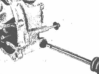
Remove the cover and leash roller
34. Remove the bushing with the reverse gear selector spring.
35. Carefully remove the bearing rings (photo).
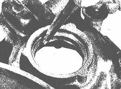
Knock out the bearing ring
36. Remove the gear shift rod seal from the crankcase.
37. Remove the drive shaft seals from the crankcase by knocking them out with a hammer and punch.
38. Remove the differential bearing ring.
39. Remove the breather deflector.
40. Remove the control lever spring.