


Note: Observe absolute cleanliness when working. Even slight contamination will damage the CV joint.
Grease for CV joints of Ford KA model:
- Amount of grease for inner CV joint: 100 g.
- Amount of grease for outer CV joint: 40 g.
Grease for CV joints of Ford Fiesta/Mazda 121 models:
- Amount of grease for inner CV joint: 125 g.
- Amount of grease for outer CV joint: 30 g (diesel models - 40 g).
Ford lubricant specification: WSD-M1C230-A.
Defective balls in bearings are manifested by beating when the load changes and by noise. In this case, the CV joint must be replaced.
Inner cover (from the gearbox side)
Removal
Support the car from the front.
If present, remove the lower engine compartment cover.
Disconnect the wishbone from the steering knuckle.
Disconnect the steering rod from the steering knuckle.
Disconnect the anti-roll bar connecting rod from the shock absorber strut.
Mark the installation position of the boot on the drive shaft.
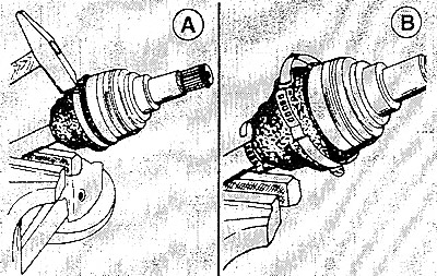
Loosen the band clamps with a hammer and remove them.
Slide the cover onto the drive shaft.
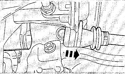
Pull out and remove the drive shaft with the tripod CV joint from the gearbox housing.
[The full text is on the website: mazbook.ru]
Thoroughly wash the CV joint cavity, internal parts, flanges, caps and covers. Remove old grease with solvent or compressed air.
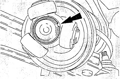
Spread and remove the tripod retaining ring with suitable pliers.
Pull the tripod off the drive shaft.
Pull the boot off the drive shaft.
Installation
Lightly lubricate the surface of the drive shaft to make it easier to put on the cover.
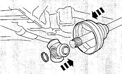
Place the new boot with the mounting tape on the drive shaft.
Place the tripod on the splines of the drive shaft, making sure that the beveled side of the tripod joint is facing the drive shaft.
Place a new retaining ring on and secure it in place.
Fill the tripod joint with fresh special grease and insert it into the CV joint housing. Push the joint all the way in, then pull it out 20 mm. Make sure that as little grease as possible gets into the boot. The amount of grease is given above in this section.
Place the boot on the CV joint housing and align it according to the marks made during removal.
Note: The corrugated cover should not be retracted after installation. If necessary, insert a small screwdriver under the cover slot and remove air from the cover.
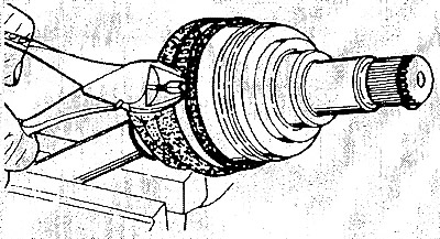
Ford Fiesta/Mazda 121: Install new band clamps and tighten them by hand first, then tighten with pliers.
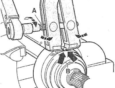
Step 1: Tighten the tie strips with a special clip. Position the clamp as shown in the figure, the jaws of the clamp should fit against the edges (B). In this position, tighten the bolt (A) with a torque wrench, which will tighten the tie belt.
Tightening torque:
- 12 Nm for tape thickness 0.8 mm;
- 20 Nm for tape thickness 1.1 mm.
Caution: The clamp thread must be clean, if necessary lubricate it with molybdenum grease.
Install the stabilizer connecting rod onto the shock absorber strut and tighten its mounting nut to a torque of 50 Nm.
Install the wishbone onto the steering knuckle.
Install the tie rod end onto the steering knuckle.
If removed, install the lower engine compartment cover.
Lower the car.
Outer cover (from the wheel side)
Removal
Raise and support the vehicle from the front.
If present, remove the lower engine compartment cover.
Remove the wishbone from the steering knuckle.
Remove the tie rod end from the steering knuckle.
Remove the connecting rod for the anti-roll bar from the shock absorber strut.
Mark the installation position of the boot on the drive shaft.
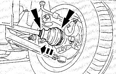
Loosen the band clamp with a hammer and remove it.
Slide the cover onto the drive shaft.
Thoroughly wash the CV joint cavity, internal parts, flange, protective caps and covers. Remove old grease with solvent or compressed air.
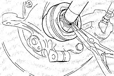
Spread the retaining ring with special pliers and remove it.
Carefully push the wheel suspension outward and pull the CV joint off the shaft.
Pull the boot off the drive shaft.
Installation
Check the working surfaces and balls for wear; replace the CV joint if necessary.
Lightly lubricate the surface of the shaft to make the cover easier to put on.
Place a new boot on the drive shaft.
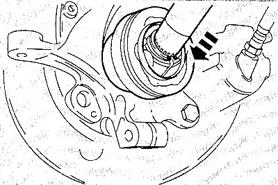
Insert a new retaining ring into the groove on the CV joint.
Carefully press the wheel suspension outward and insert the shaft into the CV joint until the locking ring is locked.
Fill the CV joint cavity with 30 g (diesel models - 40 g) fresh special grease. Make sure that as little grease as possible gets into the cover.
Note: The amount of grease for Ford KA is 40 g.
Place the cover over the CV joint housing and align it according to the previously made marks.
Note: The corrugated cover should not be pulled in after installation. If necessary, push a small screwdriver under the edge of the cover and remove the air.
Ford Fiesta/Mazda 121: Install new band clamps and first squeeze them by hand. Then tighten with pliers.
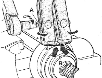
Step 1: Squeeze the tie strips with a special clamp. Position the clamp as shown in the figure, the jaws of the clamp should fit against the edges (B). In this position, tighten the bolt (A) with a torque wrench, which tightens the tie belt.
Tightening torque:
- 12 Nm for tape thickness 0.8 mm;
- 20 Nm for tape thickness 1.1 mm.
Install the connecting rod for the stabilizer on the shock absorber strut and tighten its mounting nut to a torque of 50 Nm.
Install the wishbone onto the steering knuckle.
Install the tie rod end onto the steering knuckle.
If removed, install the lower engine compartment cover.
Lower the car.