


Removing
Disconnect the negative cable from the battery with the ignition off.
Attention: This will erase the data from the electronic memory blocks. See instructions in chapter «electrical equipment».
Loosen the center axle nut. In this case, the car must be on the ground, because. she's in a big moment. Pre-bend the safety tab.
Loosen the upper shock strut mounting nut with a 1-9mm socket wrench while holding the shock absorber stem with a 6mm hex wrench to prevent the stem from turning.
Mark the position of the front wheel in relation to the hub so that the balanced wheel can then be set in the same position. Loosen the wheel nuts while the vehicle is on the ground. Raise and support the car in front, remove the front wheel.
Remove the brake hose holder.
Remove brake caliper.
Hang the caliper on the wire on the body so that the brake hose is not twisted or strained. The brake hose remains connected, otherwise the brakes will need to be bled after reassembly.
Pull the tie rod end out of the steering knuckle.
Attention: After removing the steering knuckle, wrap the tie rod end with a cloth so as not to damage it.
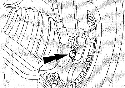
If so, unscrew the anti-lock brake sensor.
Unscrew the axle nut and remove it together with the washer.
Remove brake disc.
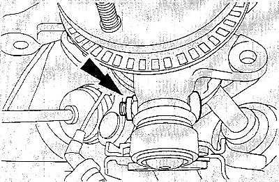
Loosen clamping bolt and nut (arrow) front axle hinge. Pull the control arm DOWN out of the steering knuckle.
Attention: Make sure that the rubber boot of the ball joint is not damaged. For protection, wrap the cover with a rag.
Using a puller, remove the steering knuckle from the drive shaft.
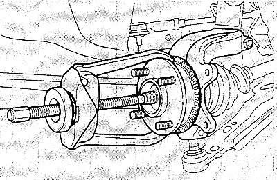
Caution: When doing this, make sure that the drive shaft does not come loose from the inner CV joint.
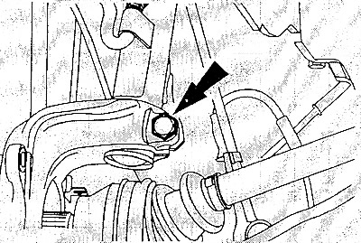
Unscrew the spring strut clamping bolt on the steering knuckle.
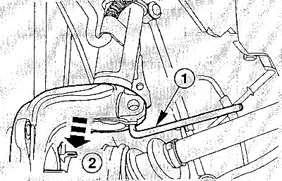
Spread the knuckle clamp with a suitable tool (1). To do this, insert the tool into the slot (clamp) knuckle and rotate its lever by 90°.
Pull the steering knuckle down (2).
Installation
Slide the steering knuckle onto the suspension strut and align it. Remove the knuckle release tool.
Insert a new self-locking spring strut clamp bolt onto the steering knuckle, making sure that the bolt passes through the slot in the mounting plate. Tighten clamping bolt to 85 Nm.
Slide the steering knuckle onto the drive shaft.
Screw in the new axle nut until it stops, but do not tighten it yet.
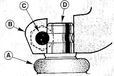
Press the ball joint of the control arm from below to the stop into the steering knuckle (IN). Insert bolt (WITH) at the front, it fits into a groove on the control arm trunnion (D). (A - dust cover).
Attention: The head of the bolt must point in the direction of travel, i.e. forward. Tighten the new self-locking bolt nut to 50 Nm.
If removed, screw in the ABS sensor and tighten to 10 Nm.
Install the brake disc and secure it with a new clamp.
Install the brake caliper.
If the brake hose was disconnected, bleed the air from the brakes.
Insert the tie rod end into the steering knuckle and secure it with a new nut, tightening it to 35 Nm. While doing this, hold the pin with a hex wrench.
Install the front wheel in accordance with the marks made earlier. Lightly coat the centering holes on the disc with grease. Do not lubricate the threads of the wheel studs. Install the wheel. Lower the vehicle and tighten the wheel nuts crosswise to 90 Nm.
Tighten the upper suspension strut nut to 50 Nm while holding the shock absorber rod with a hexagon wrench.
Note: To ensure that the nut can be tightened to the correct torque, a special spanner must be used.
Tighten the axle nut to 270 Nm and bend the latch tab.
Attention: The car must be on the ground.
Check the freedom of movement of the brake hose and wires of the anti-lock sensor. To do this, the assistant must turn the front wheels left and right as far as they will go.
Connect the negative cable to the battery, set the clock and enter the necessary codes.