
Note: For the Ford Fiesta and Mazda 121 to be able to remove the right drive shaft, the left drive shaft must first be removed.
For Ford KA models, the right drive shaft is removed in the same way as the left one. If the balancing weight is removed, the distance to the end of the drive shaft must be measured and recorded. Then you need to install the load in the same position.
When only the covers need to be replaced, the drive shafts do not need to be completely removed.
Removing
Loosen the upper suspension strut nuts five turns.
Attention: The nuts do not need to be replaced.
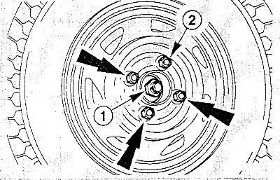
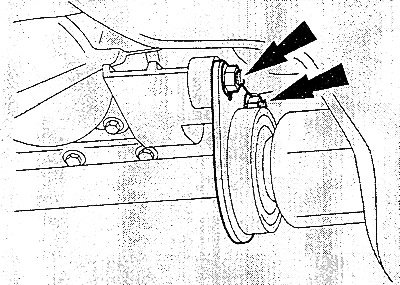
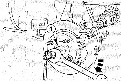
Bend the tab of the axle nut retainer (1) using a rod.
Loosen the axle nut with a 32 mm spanner. If necessary, have an assistant keep the brake pedal depressed to keep the front wheels from spinning.
Precautions: when unscrewing the axle nut, the car must be on the ground, because. the nut is very tight.
Mark the position of the front wheels on the hubs so that the balanced wheels can then be set to the same positions. Loosen the wheel nuts with the vehicle on the ground. Support the vehicle at the front and remove the front wheels.
If so, remove the lower engine compartment cover.
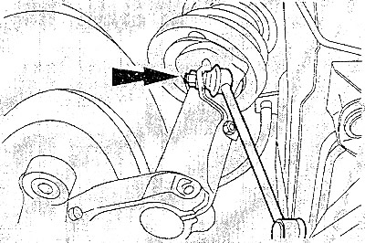
Disconnect the control arm from the steering knuckle.
Disconnect tie rods from steering knuckles.
Loosen the nuts and remove the anti-roll bar connecting rods from the suspension struts.
Unscrew the axle nut and remove it together with the washer from the end of the drive shaft.
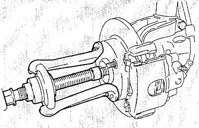
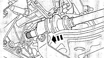
Using a suitable puller, pull the drive shaft out of the wheel hub seat.
Pull steering knuckle out and remove drive shaft from steering knuckle. To avoid unacceptable loading of the inner CV joint, hang the drive shaft on a wire. The maximum allowable tilt angle of the CV joint on the gearbox side is 18°; the outer CV joint has a stop, but the drive shaft is not pressed against the stop with force.
Place a container to collect oil under the inner one. CV joint and gearbox.
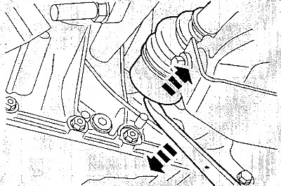
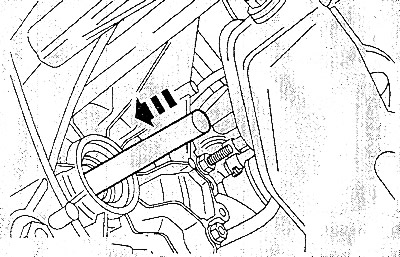
Press the left drive shaft out of the gearbox.
To do this, insert a large pry bar between the CV joint and the gearbox housing. Turn the pry bar and push out the CV joint.
Attention: When doing this, use wooden pads so as not to damage the gearbox. Do not pull on the drive shaft!
Attention: When pulling out the shaft, oil flows out of the gearbox. Seal the opening in the gearbox with a suitable plug.
Unscrew the nuts and remove the intermediate shaft bearing from the front axle beam.
Drive the right drive shaft out of the gearbox with a suitable soft metal rod from the opposite side. Leave the rod in the gearbox until the right drive shaft is installed.
Close the hole with a suitable plug.
Installation
Before installation, check the wear of the drive shaft seal in the gearbox housing.
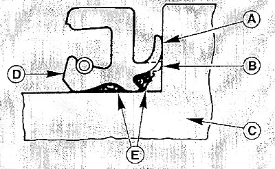
A. Sealing lip of a new oil seal; B. Sealing lip of a worn oil seal; C. Wheel hub or drive shaft; D. Oil seal; E. Lubrication.
Pull out the worn oil seal with a screwdriver, without damaging the gearbox housing.
Attention: If the oil seal is damaged or worn, check the rollers and the bearing rings for damage and replace if necessary.
Lubricate the new oil seal as shown in the illustration and push it evenly with a suitable tube.
Replace all circlips, self-locking nuts and cotter pins. When installing the drive shafts, make sure that the circlip is correctly seated.
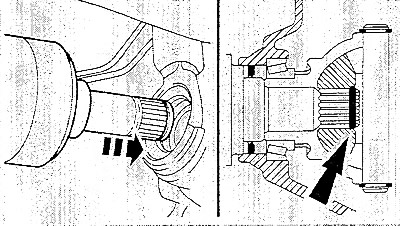
Insert the right drive shaft with a new circlip into the gearbox and secure with firm pressure. By lightly pressing and pulling, check whether the shaft is fixed.
Fit intermediate shaft bearing and tighten nuts to 25 Nm.
Insert the left drive shaft into the gearbox and fix it.
Pull the steering knuckle outwards and insert the drive shaft by hand into the wheel bearing. Insert the washer, screw in the old axle nut and, by tightening the nut, push the wheel hub onto the end of the drive shaft. Do not tighten the axle nut. Finally, unscrew the nut and replace it with a new one.
Attention: If the nut is not put on, then pull the hub onto the shaft until it stops using the special tool. At the same time, turn the wheel hub so that the wheel bearing sits evenly in place.
Tighten the new axle nut with washer by hand until they are in contact with the hub, but do not tighten yet.
Install the stabilizer bar connecting rods on the suspension struts and tighten the nuts to a torque of 50 Nm.
Install the control arm to the steering knuckle.
Install the tie rod end to the steering knuckle. '
If removed, install lower engine compartment cover.
Install the front wheels in accordance with the marks made earlier. Before doing this, lightly grease the centering hole on the wheel rim with grease. Do not lubricate the threads of the wheel studs. Tighten the wheel nuts. Lower the vehicle and tighten the wheel nuts crosswise to 90 Nm.
Tighten the axle nut to 270 Nm and secure it.
Tighten the upper suspension strut nuts to 90 Nm.
Check the freedom of movement of the brake hoses and sensor wires for the anti-lock system. To do this, the assistant must turn the front wheels to the right and left as far as they will go.
Check the oil level in the gearbox and top up if necessary.