
Checking the voltage on the contacts of the 10-pin socket (Mazda)
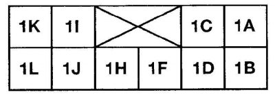
Mode | Contact | Voltage |
Air mixture knob in any position | 1A | #6.0 |
Air mixture knob in any position | 1B | No |
Air mixture control knob in the COLD position (cold) | 1C | B+ |
Temperature control lever in HOT position (hot) | 1D | 5 |
Temperature control lever in COLD position (cold) | 1D | #1 |
Air mixture control knob in HOT position (hot), Temperature adjustment lever moved from COLD to HOT | 1F | B+ |
Ventilation switch on: | ||
Mode switch moves from DEF to VENT | 1H | B+ |
Window heater switch on: | ||
Mode switch moves from VENT to DEF | 1I | B+ |
Any Mode | 1J | No |
Ignition on | 1L | B+ |
Checking the voltage on the contacts of the 14-pin socket (Mazda)
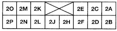
Mode | Contact | Voltage |
| Window heater switch on: | ||
Mode switch moves from VENT to DEF | 2A | No |
Light switch in position Max | 2B | No |
Light switch in position Min | 2B | #10 |
| Ventilation switch on: | ||
Mode switch moves from DEF to VENT | 2C | B+ |
Light switch on | 2D | B+ |
Fan switch off | 2E | B+ |
| Fan switch on | 2F | No |
| Fresh air switch on | 2H | B+ |
| Air recirculation switch on | 2J | B+ |
| Window heater switch on | 2K | No |
| General heating and window heating switch on | 2L | No |
| Heating switch on | 2M | No |
| Ventilation switch on | 2N | No |
| Double Deck Switch On | 2O | No |
| Ignition on | 2P | B+ |
| Oscillation switch on | 2P | #1 |
Removal and installation
1. Disconnect the negative battery cable.
2. Remove the center console.
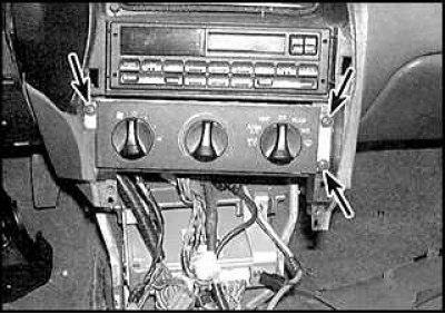
3. Unscrew the four screws of the control box (indicated by arrows).
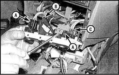
4. Remove the block and disconnect the wires and control cable from it.
5. Installation is carried out in the reverse order of removal.
Cable adjustment (Ford)
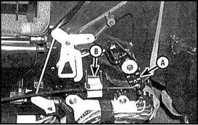
To adjust the cable, set the temperature control lever to the highest temperature position. Release the end of the cable from the clip, push the choke lever down and tighten the cable clip.
Checking the electrical circuit (Mazda)
There are three pin sockets on the back of the control box, 10-pin, 14-pin and 6-pin. Using diagrams (see fig. Checking the voltage on the contacts of the 10-pin socket (Mazda), see fig. Checking the voltage on the contacts of the 14-pin socket (Mazda)), check the operation of the control box switches.