
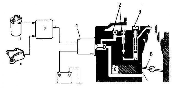
Supply air temperature control (hot air supply system)
Inlet air temperature control system
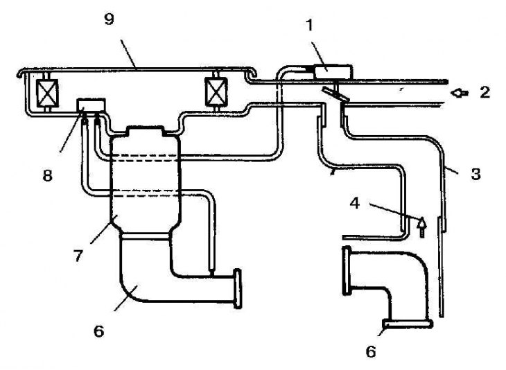
1. Vacuum diaphragm; 2. Cold air; 3. Hot air hose; 4. Hot air; 5. Exhaust manifold 6. Intake manifold; 7. Carburetor; 8. Temperature valve; 9. Air filter
The air filter intake flap opens or closes depending on the temperature in the engine compartment. The vacuum from the intake manifold flows through a thin hose to the vacuum diaphragm, which controls the position of the damper in the air intake duct. Another hose connects the first hose (through a tee) with a temperature sensor located in the air filter housing. The temperature sensor is a bimetallic valve that closes and opens the ventilation duct. When the temperature in the engine compartment rises, the valve opens, allowing air to pass through, which eliminates the vacuum at the vacuum diaphragm.
When the temperature in the engine compartment is low, the bimetal valve is closed and the vacuum acts on the vacuum diaphragm, which fully opens the damper. Hot air from the exhaust manifold enters the intake port of the carburetor. When the temperature in the engine compartment rises, the bimetal valve begins to open, which reduces the vacuum acting on the vacuum diaphragm, which begins to close the damper.
A mixture of hot air and cold outside air is now entering the carburetor. When the temperature in the engine compartment rises above about 30°C, the bimetal valve opens fully; The damper completely closes the flow of hot air from the exhaust manifold. Warm air from the engine compartment enters the carburetor. Thus, the temperature of the air entering the carburetor is kept approximately constant regardless of the temperature of the outside air (or temperature in the engine compartment).
An optional vacuum valve can be used to maintain a constant supply of hot air during hard acceleration.
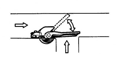
On some models, a bimetal spring is used, which is directly connected to the air damper. The bimetal spring directly regulates the position of the air damper, opening or closing it, depending on the ambient temperature.
Intake air temperature control system using a bimetal valve
Internal fuel and air valves
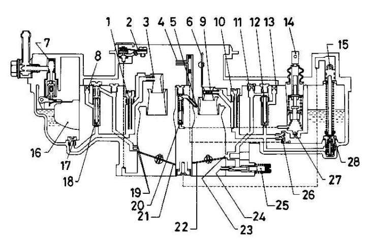
1. Main air jet - secondary chamber; 2. Temperature compensator of the idling system at high engine temperature; 3. Atomizer - secondary chamber; 4. Outlet of enrichment device; 5. Accelerator pump atomizer; 6. Air damper; 7. Fuel filter; 8. Transient mode air jet - secondary chamber; 9. Atomizer - primary chamber; 10. Main air jet - primary chamber; 11. Air jet of the idle system - primary chamber; 12. Fuel jet of the idle system - primary chamber; 13. Air jet with a reduced flow area of the idle system - the primary chamber; 14. Accelerator pump piston; 15. Plunger of enrichment device; 16. Float; 17. Main fuel jet - secondary chamber; 18. Transient jet - secondary chamber; 19. Openings of the transition mode - the secondary chamber; 20. Graduation ball clan; 21. Throttle valve - secondary chamber; 22. Throttle valve - primary chamber; 23. Openings of the transition mode - the primary chamber; 24. The opening of the idle system - the primary chamber; 25. Screw for adjusting the amount of idle mixture; 26. Main fuel jet - primary chamber; 27. Inlet ball valve; 28. Enrichment device valve
Dosing system
Fuel enters the carburetor through a fine mesh filter. The fuel level in the float chamber is controlled by a needle valve or a plastic float.
The float chamber has an internal vent opening to the area behind the air filter.
Idle system and transition system
Fuel from the fuel well enters through the calibrated jet of the idle system into the idle channel. Here, the fuel is mixed with a small amount of air entering through a calibrated air jet. Further, the fuel mixture passes through a jet with a reduced flow area. The resulting mixture passes through the channel and is released from the hole under the throttle valve of the primary chamber. The conical mixture adjusting screw is used to change the flow area of the hole, which allows for fine adjustment of the amount of idle mixture. Multiple transient holes (or transient groove) provide a rich mixture when they open when the throttle is opened. This system ensures that there are no failures in the operation of the engine at the time of opening the throttle.
The idle speed of the engine is controlled by the adjusting screw. The adjusting screw is tightened so that the toxicity of the exhaust gases is in line with the norm, and is closed with a cap.
Fuel cut-off valve
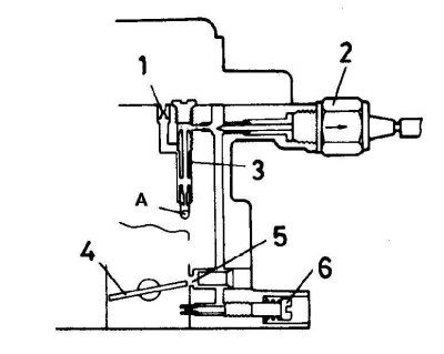
1. Air jet of the idle system - primary chamber; 2. Fuel cut-off valve; 3. Fuel jet of the idle system - primary chamber; 4. Throttle valve - primary chamber; 5. Openings of the transition mode - the primary chamber; 6. Idle mixture adjustment screw A. To the main fuel jet of the primary chamber
The fuel shutoff valve is used to prevent fuel from entering the engine after the engine has been turned off. The valve has an operating voltage of 12 volts and uses a plunger to block the idle channel when the ignition is turned off.
On some models, the valve is controlled by an electronic control unit. The valve can also be activated by a strong reduction in the speed of the crankshaft with a closed throttle. This saves fuel and reduces emissions. When the engine speed drops below a certain level, or if the throttle valve opens, the electronic control unit opens the valve and normal fuel supply is restored. The connection of the electronic control unit differs depending on the model.
The system of lean fuel mixture with a decrease in the frequency of revolutions of the crankshaft (installed on some models)
As the engine speed decreases, the lean solenoid valve lets more air into the carburetor's secondary mixing chamber. The system helps to improve fuel combustion and, consequently, reduce the content of unburned hydrocarbons in the exhaust gases.
The system of enrichment of the fuel mixture with a decrease in the frequency of revolutions of the crankshaft (installed on some models)
As the engine speed decreases, the enrichment solenoid valve allows additional air and fuel into the carburetor's secondary mixing chamber. The system helps to improve fuel combustion and, consequently, reduce the content of unburned hydrocarbons in the exhaust gases.
Fuel from the fuel well of the secondary chamber enters the enrichment channel through a calibrated jet. Here it mixes with a small amount of air entering through two calibrated air jets. The resulting mixture passes through the channel and is released from the hole under the throttle valve of the secondary chamber. The operation of the system is controlled by an electronic control unit. The system is activated when the crankshaft speed drops from 1500 - 2300 rpm. The ECM receives information from the throttle switch and the ignition coil and uses this information to determine when to energize the solenoid valve.
System for correcting the fuel mixture when reducing the frequency of revolutions of the crankshaft of the engine
1. The solenoid valve of the fuel mixture correction system; 2. Air jets of the fuel mixture correction system; 3. Air jet of the main dosing system - secondary chamber; 4. Jet of the fuel mixture correction system 5. Throttle valve - secondary chamber; 6. The switch of system of idling; 7. Ignition coil; 8. Electronic engine control unit
Throttle damper (installed on some models)
When the throttle closes abruptly, there is a sharp increase in vacuum in the intake manifold, which can lead to the evaporation of fuel droplets located on the walls of the intake manifold. This additional fuel often passes through the engine's cylinders without being completely burned, resulting in an increase in unburned hydrocarbons in the exhaust gases. Also, on models with an automatic transmission or emission reduction system, a sharp lean fuel mixture can cause poor engine response or the engine may stall altogether. Vacuum Throttle Damper allows the throttle to close gradually, which reduces engine speed without increasing emissions or impairing engine performance.
Throttle valve positioning mechanism when engine speed is reduced (installed on some models)
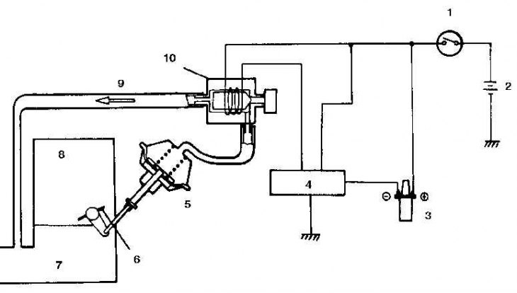
1. Ignition lock; 2. Battery; 3. Ignition coil; 4. Electronic control unit; 5. Diaphragm; 6. Throttle valve of the primary chamber; 7. Intake manifold; 8. Carburetor; 9. Vacuum from the intake manifold; 10. Solenoid valve for throttle positioning system
The throttle positioning mechanism works similarly to a throttle damper. However, the positioning mechanism is controlled by a solenoid valve and an electronic control unit to ensure that the throttle remains slightly ajar when the crankshaft speed is reduced. The throttle positioner diaphragm is usually also used by the idle control system.
System for increasing the speed of the crankshaft when idling (models with hydraulic power steering)
Vehicles with power steering may use an idle boost system that is activated when the steering wheel is turned. Since the power steering pump is driven by the engine, when the steering wheel is turned and the pump is turned on, the idle speed decreases.
When the wheels are turned, the switch in the power steering system closes the solenoid valve circuit of the crankshaft speed increase system. The vacuum is supplied to the diaphragm of the throttle positioning mechanism, which slightly opens the throttle. When the load is removed from the engine, the power steering system switch opens the circuit, and the solenoid valve closes the vacuum supply to the diaphragm; the vacuum at the diaphragm disappears and the throttle valve returns to its normal idle position.
High Idle Temperature Compensator - Some Models
The high idle temperature compensator is a temperature sensitive device that is installed between the air filter intake pipe and the intake manifold. It serves to prevent poor engine operation when hot (when the engine is idling for a long time in hot weather, for example). When the temperature in the engine compartment becomes too high, the fuel in the float chamber expands and the level rises, resulting in a mixture that is too rich. The temperature compensator is used to supply additional air to avoid the formation of a supersaturated mixture.
The compensator is closed at normal temperature in the engine compartment. When the temperature in the engine compartment rises above 67°C, the valve begins to open and additional air enters the intake manifold to dilute the rich fuel mixture. The compensator is fully open when the temperature in the engine compartment rises above 71°C. When the temperature in the engine compartment returns to normal (below 71°С), the valve closes, cutting off the air supply.
Accelerator pump
The Nikki carburetor's accelerator pump is controlled by a piston. The accelerator pump control drive is mechanical and is carried out using a lever connected to the primary chamber throttle control mechanism.
When the accelerator pedal is depressed, a lever connected to the throttle valve coupling mechanism presses on the accelerator pump piston. Fuel from the pump chamber is forced into the pump outlets through the outlet valve (with weight) and enters the mixing chamber through the pump sprayer. Inlet (ball) the valve remains closed to prevent fuel from flowing back into the float chamber.
When the accelerator pedal is released, the spring returns the piston to its original position. The vacuum draws a new portion of fuel from the float chamber into the pump chamber through the exhaust (ball) valve.
Main dosing system
The amount of fuel released into the air stream is controlled by a calibrated main fuel jet. Fuel enters through the main fuel jet to the base of the vertical fuel well, which is lowered into the fuel in the float chamber with its lower end. The emulsion tube, closed by an air jet, is installed in the well. The fuel is mixed with air entering through the air jet and through the holes in the emulsion tube, the resulting emulsified mixture is released through the atomizer into the diffuser of the primary chamber of the carburetor.
Enrichment of the fuel mixture at partial engine load
The air channel goes from the throttle space to the enrichment chamber. When the engine is idling and at low throttle opening, the vacuum from the intake manifold in the channel takes the plunger away from the enrichment valve. The valve closes, closing the fuel outlet port. As the engine speed increases, when the throttle valve opens more, the vacuum in the intake manifold decreases. The plunger returns to its original position under spring pressure and presses on the valve, which opens the fuel channel. Fuel from the float chamber through the channel enters the main fuel well; the fuel level in the well rises, resulting in a richer fuel mixture.
The work of the secondary chamber of the carburetor
There is an air channel in both the primary and secondary mixing chambers of the carburetor. Air flows from these channels enter one common channel, which leads to a diaphragm that controls the position of the throttle valve of the secondary chamber. At low engine speeds, only the primary mixing chamber is used. When the speed of the air flow passing through the primary chamber reaches a certain level, the vacuum acts through the channel on the diaphragm of the secondary chamber, which opens the throttle valve of the secondary chamber. The vacuum formed in the secondary chamber further controls the opening speed of the throttle valve in the secondary chamber.
The primary throttle link mechanism serves to prevent the secondary throttle from opening when the airflow rate is too high but the accelerator pedal is not depressed. The secondary chamber will not engage until the primary chamber throttle is approximately half open. After opening the throttle valve of the secondary chamber, the operation of the dosing system of the secondary chamber is similar to that of the main dosing system.
The transient jet is used to prevent engine stalling when the secondary throttle begins to open. Fuel from the fuel well of the secondary chamber passes through a calibrated jet. Then, it mixes with air entering through a calibrated air jet to form a fuel emulsion. This emulsified mixture is released into the secondary mixing chamber, through the transition port, when the secondary chamber throttle valve starts to open.
Mechanical air damper
The drive of the mechanical air damper is cable. When the control button on the instrument panel is pulled out, the connecting cable moves a lever that causes the choke to close the air intake duct. The fast idle mode is activated by a cam connected to the choke lever. The adjusting screw, mounted on the throttle lever and resting against the cam, is used to adjust the engine speed when the engine is running at fast idle.
Opening the air damper
After starting the engine, the choke should open slightly to form a less saturated fuel mixture and prevent fuel overflow. This is achieved by using intake manifold vacuum which acts on the diaphragm; the diaphragm coupling mechanism opens the air damper.
Automatic choke
Some Nikki carburetor models have an automatic starter. The position of the air damper is regulated either by a bimetallic coil with electrical heating (semi-automatic air damper) or temperature wax switch heated by engine coolant (fully automatic air damper).
Semi automatic air damper
To adjust the position of the semi-automatic air damper, an electrically heated bimetal coil is used. The system is reset by slowly depressing the accelerator pedal once or twice. After starting the engine, power from the generator is supplied to the ceramic heater, which heats up quickly. Heat is transferred to the bimetallic spiral through the sleeve; when the bimetal coil heats up, it unwinds, opening the air damper.
Fully automatic air damper
A wax capsule is used to adjust the auto choke position. The capsule is heated by the engine coolant. When the coolant temperature is low, the wax capsule is completely compressed - the air damper is closed. After starting the engine and during warm-up, heat from the heating engine coolant acts on the wax capsule, which begins to gradually expand; the expanding capsule gradually opens the air damper. When the coolant temperature reaches the normal operating level, the choke will be fully open.
Both types
After starting the engine, the choke should open slightly to form a less saturated fuel mixture and prevent fuel overflow when the engine is idling and at low throttle. This is achieved by using intake manifold vacuum which acts on the diaphragm; the diaphragm coupling mechanism opens the air damper. Some models have a second opening diaphragm. It is controlled by a thermal vacuum valve and is used to ensure that when the engine temperature rises above a certain value, the air damper also opens more.
The fast idle mode is activated using a toothed cam connected to the choke shaft through a connecting rod. The fast idle lever, connected to the throttle lever, presses against the toothed cam. When the bimetal coil heats up and the air damper opens, the lever moves down over the teeth of the cam. Thus, the idle speed is gradually reduced until the fast idle cam is free and the idle speed decreases to normal. The adjustment screw connected to the fast idle lever can be used to adjust the fast idle speed.
If the throttle is fully opened when the engine temperature is low, the vacuum at the choke diaphragm will disappear, causing the choke to close. This may cause fuel overflow. To prevent this, a mechanism for partially opening the air damper is used. When the throttle is fully opened, the throttle lever moves down to slightly open the choke.