
Nikki carburetor parts - automatic choke model
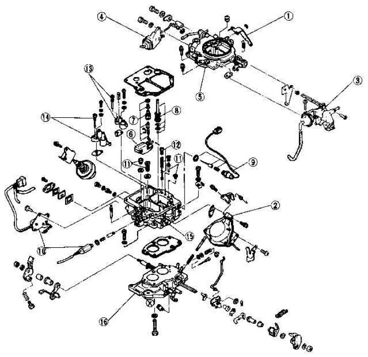
1. Accelerator pump lever; 2. Throttle diaphragm - secondary chamber; 3. Wax capsule and air damper opening mechanism; 4. Diaphragm of the safety device of the fast idle system; 5. Carburetor cover; 6. float; 7. Needle valve; 8. Accelerator pump; 9. Shut-off valve; 10. The solenoid valve of the crankshaft speed increase system and the idle system switch; 11. Air and fuel jets; 12. Accelerator pump spray weight; 13. Diffuser and emulsion tube - primary chamber; 14. Diffuser and emulsion tube - secondary chamber; 15. Carburetor body; 16. Choke body
The location of the jets
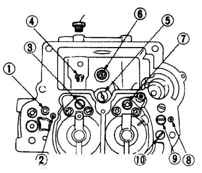
1. Transient jet - secondary chamber; 2. Transient mode air jet - secondary chamber; 3. Main air jet - secondary chamber; 4. Main fuel jet - secondary chamber; 5. Fuel jet enrichment device; 6. Main fuel jet - primary chamber; 7. Main air jet - primary chamber; 8. Air jet of the idle system - primary chamber; 9. Fuel jet of the idle system - primary chamber; 10. Air jet of the idle system - primary chamber
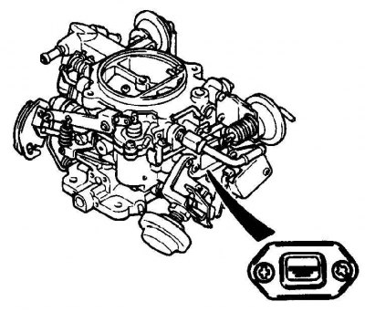
Float chamber window
Disassembly and inspection
1. Remove the carburetor from the engine.
2. Inspect the carburetor for damage or wear.
3. Disconnect the throttle return spring.
4. Inspect the accelerator pump lever for signs of wear. Remove the accelerator lever retaining spring, retaining ring and clip, and disconnect the lever along with the spring.
5. Remove the clamp and disconnect the choke rod.
6. Loosen the mounting screws and remove the carburetor cover. If the cover does not come off, tap it with a rubber mallet. Do not try to pry off the carburetor cap with a screwdriver, as you may damage the mating surfaces.
7. Inspect the float chamber for corrosion and traces of calcium deposits.
8. Remove the accelerator pump outlet valve spring, circlip and ball. Turn the carburetor over and shake out these elements in the palm of your hand.
9. Unscrew the copper plug and remove the weight and spring of the inlet valve of the accelerator pump. Turn the carburetor over and shake out these elements in the palm of your hand.
10. Remove the accelerator pump piston along with seals from the carburetor cover. Check the pump piston for signs of wear or damage.
11. Knock out the float pin and remove the float, needle valve and float chamber gasket.
Attention! On some models, the needle valve seat is not removable.
12. Using a straightedge, check that the flanges of the carburetor cover, carburetor body and throttle body are not deformed.
13. Check needle valve tip for signs of wear or nicks.
14. Check the float for damage and ingress of gasoline into it; Fuel ingress into the float can be checked by shaking the float. Alternatively, lower the float into the water and see if there are any air bubbles coming out of it. Replace the float if it is out of order.
15. Check the float arm bracket for deformation, and check the float shaft mounting holes for wear or damage.
16. Replace float shaft if worn.
17. Unscrew the fuel cutoff valve (see subsection 5.1.5) and clean it with a carburetor cleaner.
18. If you have a new seal and gasket, unscrew the two screws and remove the float chamber window. Do not remove the window unless you have a new seal.
19. Remove the mixture adjustment screw. Inspect the tip of the screw for damage or nicks.
Attention! A special tool is required to remove the adjustment screw.
20. Mark the diameters of all fuel and air jets and their installation position for the correct installation of these elements when assembling the carburetor. When installing the jets are easy to confuse.
21. If necessary, remove all fuel and air jets of the primary and secondary chambers of the carburetor.
Attention! Use a short screwdriver so as not to damage the jets.
22. Unscrew the two screws and remove the diffusers. Remove the primary and secondary air jets and emulsion tubes from the diffusers.
23. Unscrew the main fuel jet of the primary chamber and remove it from the bottom of the float chamber.
24. Remove the float chamber plug and unscrew the main fuel jet of the secondary chamber from the socket on the wall of the float chamber.
25. Check the calibration of the jets by comparing their diameters with the values given in the specifications section. It is possible that the jets were incorrectly installed during the last bulkhead (or the wrong diameter jets are installed).
26. Check that all jet holes are not worn, clogged or out of round. Check that the channels connecting the float chamber to the wells of the emulsion tubes are clean.
27. Unscrew and remove the enrichment device valve from the float chamber and check its operation.
28. Check the operation of the enrichment valve plunger installed in the carburetor cap.
29. Disconnect the secondary throttle stem by removing the retaining clip. Unscrew the mounting screws and remove the diaphragm from the carburetor body.
30. Push down on the secondary throttle diaphragm rod, close the vacuum port with your finger, and release the rod. Replace diaphragm if vacuum is not maintained for at least 30 seconds
31. Loosen the fixing screws (one bottom and two top) and remove the carburetor body from the throttle body. Note the installation position of the isolation block. Using a ruler, check for deformation on the mating surfaces.
32. Check the throttle opening diaphragm (see subsection 5.1.5), and throttle damper (see subsection 5.1.5).
33. Check all vacuum hoses for cracks and signs of wear.
34. Check the choke mechanism for signs of wear and ease of movement; treat the jamming elements of the mechanism with an appropriate aerosol. If the elements of the mechanism continue to get stuck, replace them.
35. Clean the jets, carburetor cover and throttle body, float chamber and internal passages. Carefully inspect and clean all air holes and passages in the carburetor cap. Check the internal passages of the carburetor by pouring carburetor cleaning fluid into the inlets and making sure it flows out of the outlets. Flush all carburetor passages with carburetor cleaner to help clear dirt and sediment. Compressed air can be used to clean the internal channels of the carburetor, but only when the carburetor is completely disassembled.
Attention! Wear safety goggles when working with compressed air and when using carburetor cleaning fluid (if the carburetor passage is clogged, the cleaning solution may splash in your face).
Assembly
When assembling the carburetor, all gaskets must be replaced. Also, replace the needle valve and accelerator pump piston. Look around and (if it is needed) replace float pin, mixture adjustment screw and main jets. Replace worn elements of connecting mechanisms, screws, springs and other worn elements.
Check that all jets are securely screwed into their sockets (but don't twist them too tight). A loose jet can result in too rich (or even poor) fuel mixture. Clean the mating surfaces and flanges of the carburetor cover and throttle body of the old gasket and reinstall the cover with a new gasket. Do not use sealant on flanges or mating surfaces of carburetor components, or when installing a carburetor to an engine. If the sealant gets into the channels passing through the carburetor, the carburetor may fail.
Check that the fuel and air passages of the carburetor halves are correctly aligned.
1. Assemble the carburetor body and throttle body with a new gasket between them. Secure the knots with the fixing bolts.
2. Install the secondary throttle diaphragm and secure it with the mounting screws. Install the mounting clip on the diaphragm stem.
3. Screw the enrichment device valve into the float chamber.
4. Screw the main fuel jets into their sockets (don't mix up jets) and install the drain plug with a new sealing washer.
5. Install the emulsion tubes and air jets into the diffusers and put them back in place (do not mix diffusers).
6. Install the primary idle jet, plug, and air jet in their respective slots (do not confuse the elements).
7. Install the idle mixture adjustment screw and spring. Tighten the screw carefully (using a special tool if necessary), then loosen it three full turns to provide the initial adjustment to start the engine.
Attention! The thread in the carburetor hole is very thin, so you need to be very careful not to tighten the screw with a warp. If you damage the threads, the throttle body will need to be replaced.
8. Install float chamber window (if it was filmed) with new seal and gasket.
9. Install the check valve with a new sealing washer.
10. Install the hex banjo bolt with new sealing washers and tighten it lightly.
11. Install a new float chamber gasket to the carburetor body. Note: Since there are many variations of Keihin carburetors, it is important to carefully compare the old and new gaskets. A slight difference between the gaskets can cause any of the fuel or air passages to be blocked, resulting in poor engine performance.
12. Replace needle valve pin; install the float and secure it with the pin.
13. Adjust float height (see subsection 5.1.4).
14. Install the accelerator pump outlet valve weight and spring and secure with the plug.
15. Install the accelerator pump inlet valve ball, circlip and spring.
16. Install the accelerator pump piston with seals in the carburetor cover; replace seals if necessary.
17. Install the carburetor cover on the carburetor body and secure it with the fixing screws. Tighten the screws gradually and in turn so as not to deform the surface of the body or carburetor cover.
18. Connect the air damper rod and secure it with a clamp.
19. Install the accelerator pump lever and secure it with the clamp. Connect the accelerator pump return spring and throttle valve return spring.
20. Check the smoothness and progressive movement of the air damper and the connecting mechanism. Check that the coupling mechanism moves easily and is not worn.
21. Adjust the choke opening when the engine is running at fast idle, when starting and warming up the engine (see subsection 5.1.4).
22. Install the carburetor to the engine.
23. Always check the adjustment of the engine speed with the engine idling and the amount of fuel mixture idling - preferably using a CO sensor - after doing any work on the carburetor. Adjustment operations are described in subsection 5.1.4. If the carburetor has been completely disassembled, check all adjustments.