


Contents: Hot air supply system ⇓ Intake manifold heater ⇓ Temperature switch ⇓ Heater relay ⇓ Fuel shut-off valve ⇓ Fuel cut-off system when engine…⇓ Fuel mixture depletion system with…⇓ Idle speed control switch ⇓ Fuel mixture enrichment system when…⇓ Throttle damper (installed on some…⇓ Throttle positioning mechanism…⇓ Throttle positioning system diaphragm ⇓ Throttle positioning system solenoid…⇓ System for increasing the speed of…⇓ Temperature compensator of the idle…⇓ Automatic air damper ⇓ Checking the power supply ⇓
Hot air supply system
The hot air supply system check operations are described in subsection 5.1.1.
Intake manifold heater
Intake manifold heater system diagram
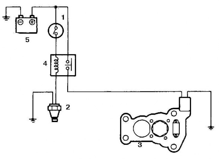
1. Ignition switch
2. Temperature switch heated by engine coolant
3. Intake manifold heater
4. Heater relay
5. Battery
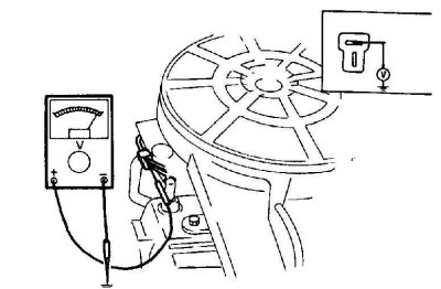
1. When the engine is cold (coolant temperature below 60°C), connect a voltmeter between the power wire on the heater (usually a thick red wire) and ground. If the voltmeter doesn't register battery voltage, check the temperature switch and heater relay.
2. Connect a voltmeter between the heater ground wire (black wire) and the "mass" of the vehicle. The voltage registered by the voltmeter should be very low (0.25 volts or less). If the voltage is higher, check the reliability of the heater grounding.
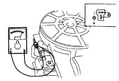
3. Disconnect the heater connection wires and connect an ohmmeter between them. Replace the heater if there is no conductivity (resistance should be 1.0 ohms or less).
Temperature switch
1. Connect a voltmeter between the temperature switch power wire and ground. The voltage reading should be very low (0.25 volts or less), since grounding is carried out through a temperature switch.
2. If the registered voltage exceeds 0.25 volts, then the temperature switch is partially or fully open. Check this by disconnecting the wires and connecting an ohmmeter between the terminals of the temperature switch. The ohmmeter should indicate that the circuit is open if the switch is open, and therefore the switch is bad. If the ohmmeter shows that the circuit is closed (which indicates that the switch is working properly), check the ground wire connecting the switch to the vehicle's ground.
3. Disconnect the ground wire, the power wire should have the rated voltage of the battery. If not, check the heater relay.
4. When the engine is hot (coolant temperature above 60°C) and the ignition is on, the voltage at the temperature switch power wire should be equal to the rated battery voltage, as the circuit should be opened by the switch.
5. If the voltage registered is lower, check the temperature switch for continuity as described above. The switch should open the circuit when the engine is hot, if not, it is faulty.
Heater relay
Intake manifold heater relay diagram
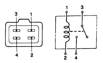
1. With the ignition on, check that terminal 1 has nominal battery voltage. If there is no potential, check the connecting wires to the ignition switch.
2. Check for nominal battery voltage at terminal 3 (when the ignition is on or off). If there is no potential, check the connecting wires to the battery.
3. Temporarily ground terminal 2 and check for battery voltage at terminal 4. If there is no potential, replace the relay.
Fuel shut-off valve
1. Turn the ignition on and then off; the valve should click when you turn the key in the ignition.
2. Connect a voltmeter between the valve power wire and ground. If the voltmeter does not indicate battery voltage, check the connecting wires to the power source (power is turned on by the ignition switch).
3. Check the operation of the valve plunger by disconnecting the shut-off valve connection connector. Temporarily connect the positive battery terminal and the valve power supply wire, as well as the negative battery terminal and the solenoid valve body with a jumper cable (or valve ground wire, if present).
4. Apply and remove voltage several times and check the plunger for smooth movement. Replace the valve if it is faulty and cleaning does not improve its performance.
Fuel cut-off system when engine speed drops (if installed)
Ground terminal on the connection connector
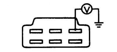
1. Connect a voltmeter between the ground terminal on the valve connection connector and the vehicle ground.
2. When the engine is idling, the voltage should be less than 1.5 volts.
3. Increase crankshaft speed; when the crankshaft speed rises above 2300 rpm, the voltmeter should show the nominal battery voltage.
Fuel mixture depletion system with reduced crankshaft speed
Using a voltmeter to test the lean fuel system
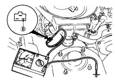
B. Terminal of the fuel mixture lean valve system
1. Warm up the engine to normal operating temperature, then connect a voltmeter between terminal "B" on the fuel mixture lean valve connector and ground.
2. Increase the crankshaft speed to approximately 3000 rpm. The voltage registered by the voltmeter should be close to zero.
3. Quickly close the throttle valve and as the engine speed decreases, the valve should make a hissing sound; the voltmeter reading should drop to zero. The voltmeter reading should then increase to the nominal battery voltage when the crankshaft speed drops below approximately 2100±100 rpm.
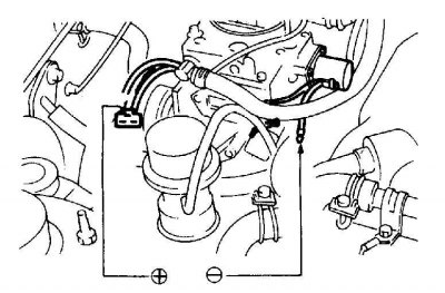
4. Check the valve plunger stroke by disconnecting the fuel mixture lean valve connector. Connect the positive (+) battery terminal and the valve power terminal with a jumper cable and the negative (-) battery terminal and the ground wire with a second jumper cable.
5. Apply and remove voltage several times; the valve should click when voltage is applied and removed.
Idle speed control switch
Using a voltmeter to test a switch
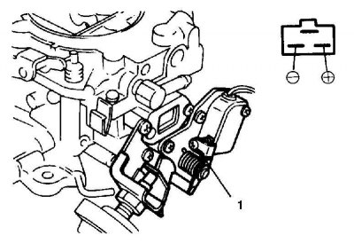
1. Adjusting screw
1. Connect a voltmeter between the two terminals on the idle speed control switch connector; when the engine is idling, the voltage should be zero.
2. Raise the engine crankshaft speed above 1250±50 rpm; the voltmeter should register the nominal voltage of the battery.
Fuel mixture enrichment system when crankshaft speed is reduced
Using a voltmeter to test the fuel enrichment system
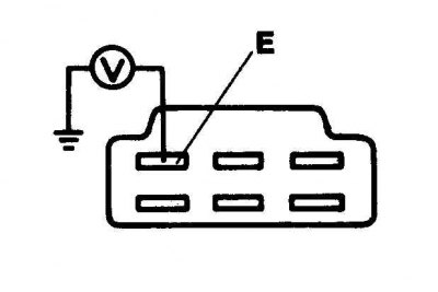
E. Ground terminal of the electromagnetic valve
Direct power supply to the fuel mixture enrichment solenoid valve
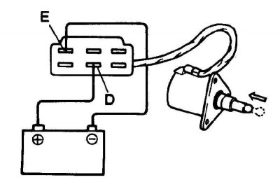
D. Solenoid valve power supply terminal
E. Ground terminal of the electromagnetic valve
1. Warm up the engine to normal operating temperature, then connect a voltmeter between terminal "E" on the fuel mixture enrichment valve connector and ground.
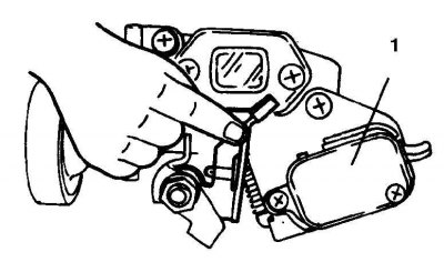
2. Raise the idle speed control switch lever to open the circuit (1 – idle speed control switch).
3. Open the throttle and increase the engine speed to approximately 3000 rpm. As the engine speed increases above approximately 2300 rpm, the voltage registered by the voltmeter should equal the nominal battery voltage.
4. Quickly close the throttle valve, and as the engine speed drops to 2300–1500 rpm, the voltmeter reading should drop below 1.5 volts. When the engine speed drops below 1500 rpm, the voltmeter reading should increase to the rated battery voltage.
5. Check the valve plunger stroke by disconnecting the fuel mixture enrichment valve connector. Connect the positive (+) battery terminal and the valve power terminal with a jumper cable and the negative (-) battery terminal and the valve ground wire with a second jumper cable.
6. Apply and remove voltage several times; the valve should click when voltage is applied and removed.
Throttle damper (installed on some models)
Adjusting the throttle damper
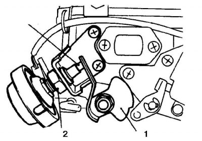
1. Lever
2. Lock nut
3. Rod
1. Warm up the engine to normal operating temperature and check that the idle speed and idle mixture quantity are adjusted correctly
2. Let the engine idle, then open the throttle and increase the engine speed to 3000 rpm.
3. Close the throttle valve completely; the damper rod should touch the throttle lever at a crankshaft speed of 2200±100 rpm.
4. Adjust the throttle damper so that the damper rod contacts the throttle lever at the specified engine speed.
5. Release the accelerator pedal and the damper should slowly return the throttle lever to the idle position.
Throttle positioning mechanism (installed on some models)
Checking the throttle positioning system
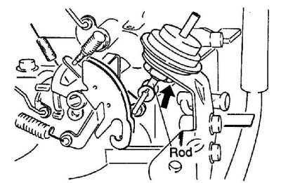
1. Rod
1. Let the engine idle, then slowly open the throttle and increase the engine speed to approximately 3000 rpm. When the engine speed rises above approximately 2000 rpm, the diaphragm positioning system diaphragm rod should be retracted by the diaphragm.
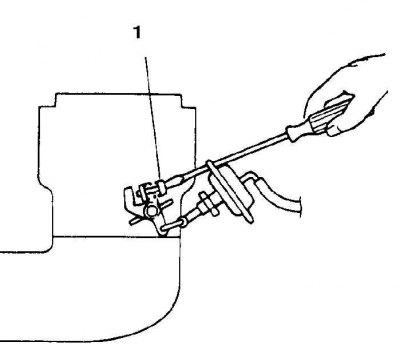
2. Close the throttle valve slowly; when the engine speed drops below approximately 1600-1800 rpm, the positioning system rod should be released to close the throttle valve.
Throttle positioning system diaphragm
Checking the diaphragm
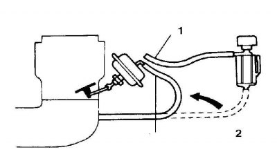
1. Disconnect the vacuum hoses from the diaphragm and plug the hose connection going to the solenoid valve (if installed).
2. Connect a vacuum pump to the vacuum port on the diaphragm and pump out air to obtain a vacuum of 300 mHg; the diaphragm should fully retract the piston rod, and the vacuum should be maintained for at least 30 seconds. Replace the diaphragm if it is faulty.
Adjustment
1. When the engine is idling (and all electrical equipment is turned off), disconnect the diaphragm vacuum hose that connects it to the throttle positioning system solenoid valve.
2. Connect a vacuum hose from the intake manifold to the diaphragm fitting, passing the throttle positioning system solenoid valve; the engine crankshaft speed should rise to 1050–1250 rpm.
3. Connect the hose from the intake manifold vacuum line to the line on the diaphragm.
4. Connect a voltmeter between the ground terminal on the solenoid valve connector and the vehicle ground.
5. Adjust the diaphragm coupling mechanism by turning the adjusting screw in the required direction.
Throttle positioning system solenoid valve
(The article is copied from the website: MazBook.ru)
Checking the Throttle Positioning System Solenoid Valve
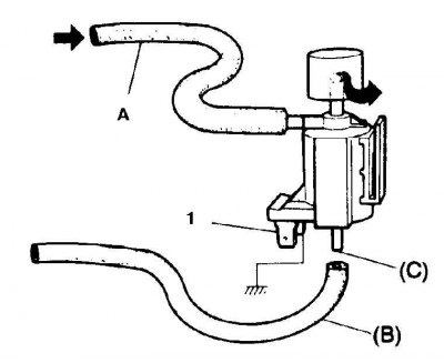
A. Hose from the intake manifold
B. Hose leading to the throttle positioning system diaphragm
S. Branch pipe
1. Supply voltage of 12 volts
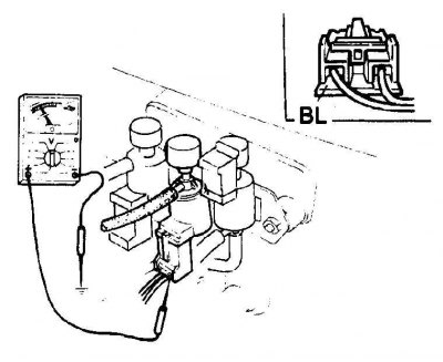
1. Connect a voltmeter between the ground terminal on the solenoid valve connector and the vehicle ground; when the engine is idling, the voltage shown by the voltmeter should be almost zero.
2. Raise the engine speed to about 3000 rpm and the voltmeter should show a voltage approximately equal to the battery voltage.
3. Slowly close the throttle valve, reducing the engine speed to approximately 1600-1800 rpm; the voltmeter reading should drop to almost zero.
4. With the engine idling, disconnect the vacuum hose connecting the solenoid valve and the vacuum diaphragm from the nipple on the solenoid valve; there should be no vacuum in the pipe.
5. Disconnect the connection connector and connect the positive battery terminal and the solenoid valve power terminal wire with a jumper cable.
6. Connect the negative battery terminal and the ground terminal of the solenoid valve with a jumper cable; a vacuum should form in the vacuum pipe.
7. If the valve does not function as required, check the connecting wires between the solenoid valve and the ECU and, if they are OK, check the ECU.
8. Reconnect the vacuum hose and connection connector after completing the check.
System for increasing the speed of rotation of the crankshaft at idle (models with power steering)
Schematic diagram of the idle speed increase system when the power steering system is engaged
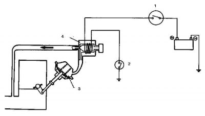
1. Ignition switch
2. Power steering system switch
3. Diaphragm
4. Solenoid valve (controlled by a switch in the power steering system)
When the engine is idling, turn the steering wheel; the throttle positioning system should activate and increase the crankshaft speed. If not, please check the following.
Temperature compensator of the idle system at high engine temperature
Temperature compensator of the idle system at high engine temperature
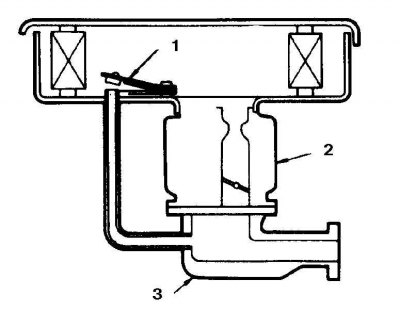
1. Compensator valve
2. Carburetor
3. Intake manifold
1. Remove the air filter.
2. Disconnect the vacuum hose going to the temperature compensator from the pipe on the carburetor and connect a vacuum pump to this hose.
3. Measure the temperature near the temperature compensator; at temperatures below 67°C the compensator must be closed. At temperatures above 71°C, the compensator should be open.
4. Wait until the compensator temperature drops below 67°C. Using a vacuum pump, evacuate the air to achieve a vacuum of 500 mmHg; this pressure should be maintained for at least 10 seconds. If not, the temperature compensator valve is partially or fully open and needs to be replaced.
5. Heat the expansion joint to a temperature above 71°C; use a vacuum pump to pump out the air – the pressure should not drop. If a vacuum is created, it means that the temperature compensator valve is not fully open and must be replaced.
Automatic air damper
Checking the power supply
The automatic air damper power supply check operations are described in subsection 5.1.1).