
Examination
Remove the protective cap and disconnect the wires from the ignition coil.
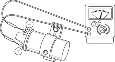
Pic. 7.3. Using an ohmmeter to measure the resistance of the primary winding of the ignition coil
To measure the resistance of the primary winding of the ignition coil, connect an ohmmeter in accordance with the circuit shown in fig. 7.3.
If the ignition coil is working properly, then there should not be an open in the circuit.
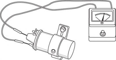
Pic. 7.4. Using an ohmmeter to measure the resistance of the secondary winding of the ignition coil
To measure the resistance of the secondary winding of the ignition coil, connect an ohmmeter in accordance with the circuit shown in fig. 7.4 and compare the obtained value with the required one.
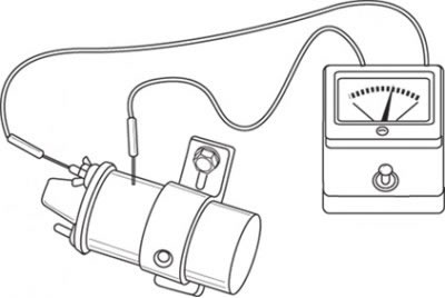
Pic. 7.5. Using an ohmmeter to measure the insulation resistance of an ignition coil
Using an ohmmeter, measure the resistance between the output of the primary winding and the ignition coil housing in accordance with the diagram shown in fig. 7.5.
If the result of one of these tests is unsatisfactory, replace the ignition coil.
Removal and installation
Disconnect the wire from the negative battery terminal.
Remove the rubber protective cap and disconnect the wires from the ignition coil, after noting their location.
Turn away bolts, remove an arm and take the coil from a collar on a radiator.
Install the coil in place and secure with bolts.
Connect the wires and put on the rubber cap securely.
Technical characteristics of the ignition coil
| Primary winding resistance, Ohm | 1,5±0,12 |
| Resistance of the secondary winding, kOhm | 10-30 |
| Resistance between the output of the primary winding and the coil body, mOhm | at least 10 |