


However, when the engine is operating under maximum load, the ignition timing should be shifted to the earliest possible point without crossing the detonation combustion limit of the fuel.
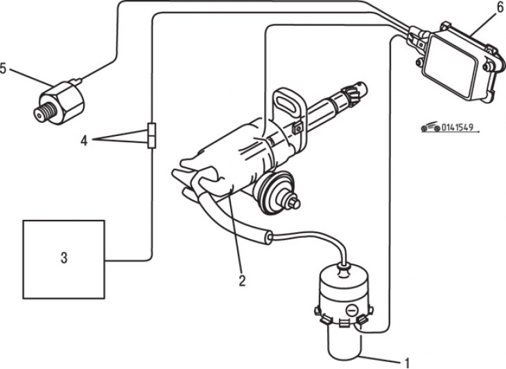
Figure 15.49. Elements of the detonation control system for fuel combustion in vehicles produced in 1986 and 1987: 1 – ignition coil; 2 – ignition distributor; 3 – control unit; 4 – diagnostic connector; 5 – knock sensor; 6 – ignition control unit
The knock control system consists of a knock sensor, an ignition timing control unit and an EGI control unit (figure 15.49). The knock sensor reacts to high-frequency vibrations of the cylinder block that occur during detonation and transforms them into electrical signals sent to the control unit. This information is then compared with signals obtained during non-knock combustion of the fuel. When detonation occurs, the ignition timing is delayed by 6°.
At an engine speed of 1650–4500 min⁻¹ or under conditions where the pressure in the intake manifold is below atmospheric pressure, the engine control unit sends a signal to the ignition control unit, which causes the ignition timing to be shifted towards an earlier position.
Please note: The following inspection procedure applies only to 1986 and 1987 model years, as servicing later models requires specialized equipment and should be performed at a service station.
(Data provided by the website: www.MazBook.ru)
Checking the knock sensor
Carefully touch the voltmeter probe to the "1U" terminal on the control unit. At idle, the voltage shown by the voltmeter should be zero. If the reading is different, check the wire from the control unit to the ignition timing control unit (terminal "G").
Check the ignition timing at idle, then disconnect the diagnostic connector from the control unit. Lightly tap the wall of the receiver with a hammer and check if the ignition timing shifts towards a later point. If the ignition timing shifts to a later point, reconnect the connector and tap the receiver wall again. Make sure that the ignition timing does not shift to a later position, which indicates that the ignition control unit is working properly. Otherwise, the control unit is faulty and must be replaced.
If the ignition timing does not advance during the first test, disconnect the diagnostic connector, connect a known-good knock sensor to the connector, and ground it. Lightly tap the sensor and check for advancement. If the ignition timing shifts to a later position, the sensor that was working is faulty. Otherwise, check the wires from the sensor to the control unit. If the wires are OK, replace the ignition control unit.
Replacement of elements
To replace the knock sensor, disconnect the connector and unscrew the sensor from the cylinder block. Installation is carried out in the reverse order of removal.
To replace the ignition control unit, disconnect the wire from the negative terminal of the battery. Disconnect the connector from the block, unscrew the two nuts and remove the block. Installation is carried out in the reverse order of removal.