


Contents: Examination ⇓ Replacement ⇓
Identifying the ignition switch terminals
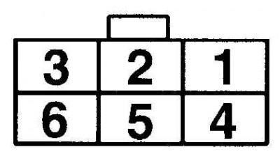
Ignition Switch Conductance Table
| Position of the key in the ignition switch | Conductivity between terminals |
| Ace | 2 and 6 |
| On | 2, 4 and 6; 1 and 5 |
| Start | 2 and 4; 3 and 5 |
Examination
1. Disconnect the negative battery cable.
2. Remove the steering column covers.
Content based on information from (mazbook.ru)
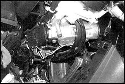
3. Disconnect the ignition switch connector.
4. Check for continuity between the switch terminals using the Ignition Switch Continuity Table.
5. Check the operation of the lock drum.
Replacement
1. Disconnect the negative battery cable. Remove the steering column covers.
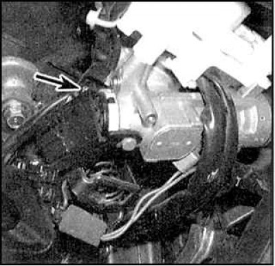
2. Disconnect the connection connector and unscrew the mounting screw (indicated by the arrow) and remove the switch.
Castle drum
3. Remove the steering column covers and lower trim panel.
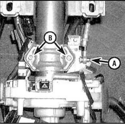
4. Disconnect the cable (A) from the ignition switch, drill out the shear bolts (B) and remove the ignition switch.
5. Drill out the mounting rivets and remove the lock drum.
6. Installation is carried out in the reverse order of removal.