


Contents: Examination ⇓ Replacement ⇓
Identification of switch terminals - models produced before 1997

Steering Column Switch Continuity Chart - Pre-1997 Models
| Combination switch | |
| Switch position | Conductivity between terminals |
| Headlights | 3 and 8 |
| Sidelights | 2 and 3 |
| Low beam headlights | 15 and 19 |
| High beam headlights | 19 and 17 |
| Flashing headlights | 17 and 18 |
| Left turn signals | 9 and 16 |
| Right turn signals | 9 and 20 |
| Emergency alarm system | 6 and 14 |
| Windscreen wiper/washer switch: | |
| - off | 4 and 13 |
| - low speed | 11 and 13 |
| - high speed | 11 and 12 |
| – windshield wipers operate intermittently | 11 and 12 |
| – windshield washers | 5 and 11 |
Combination Switch Terminal Identification - 1998 Models
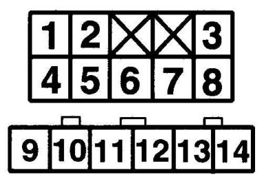
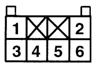
Wiper/Washer Switch Terminal Identification - 1998 Models
Conductivity table of the combination switch - 1998 model
| Switch position | Conductivity between terminals |
| Headlights | 9,10 and 11 |
| Sidelights | 10 and 11 |
| Low beam headlights | 2 and 6; 7 and 8 |
| High beam headlights | 2 and 5; 3 and 7 |
| Flashing headlights | 9 and 11 |
| Left turn signals | 12 and 14 |
| Right turn signals | 12 and 13 |
| Emergency alarm system | 6 and 14 |
Wiper/Washer Switch Continuity Chart - 1998 Models
| Switch position | Conductivity between terminals |
| Off | 3 and 5 |
| Low speed | 3 and 6 |
| High speed | 4 and 6 |
| Windscreen wipers operate with pauses 4 and 6 | |
| Windshield washers | 1 and 6 |
Examination
1. Remove the lower steering column cover and disconnect the 6-pin and 14-pin connectors.
2. Check for conductivity between the switch terminals using the tables provided in the figure Steering Column Switch Continuity Chart - Pre-1997 Models, Combination Switch Continuity Chart - 1998 Models, Windscreen Wiper/Washer Switch Continuity Chart - 1998 Models.
Replacement
Models produced before 1997
1. Disconnect the negative battery cable.
2. Remove the steering wheel and steering column covers.
3. Remove the coil spring.
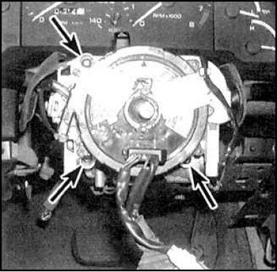
4. Loosen the mounting screws (indicated by arrows), disconnect the connection connectors and remove the switch.
5. Installation is carried out in the reverse order of removal.
1998 models
6. Remove the steering column covers.
(Article is based on website data: mazbook.ru)
7. Disconnect the connection connector, unscrew the mounting screws and remove the switch.
8. Installation is carried out in the reverse order of removal.