


Finding the source of the problem
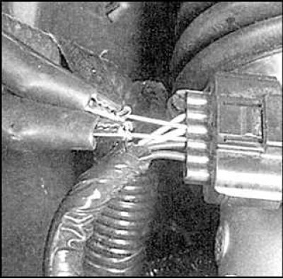
Insert a thin probe from the back of the connection socket so that it touches the desired terminal - connect a voltmeter to the probe.
A typical electrical circuit consists of an electrical element, switches, relays, motors, fuses, blown jumpers or circuit breakers of this element, wires and connectors that connect this element to the battery and car body. To assist in troubleshooting the electrical system, circuit diagrams are provided at the end of this manual.
Before attempting to determine the source of a fault, first study the relevant circuit diagram to get an idea of the elements installed in this circuit. The circle of possible sources of malfunction can be narrowed down by checking the functioning of other elements included in this circuit. If several elements or circuits fail at the same time, then the problem is obviously a fuse common to these circuits or elements, or contact with the car body.
Electrical problems are usually caused by simple causes such as loose or corroded connectors, no contact with the vehicle body, a blown fuse, a blown jumper wire, or a faulty relay. Visually check the condition of all fuses, wires and connectors in the failed circuit before proceeding to check the rest of the elements.
If you are going to use instrumentation, use the wiring diagram to determine which end clamps you need to check to find the source of the problem.
The main tools needed to locate the source of the fault are a circuit tester or a voltmeter (a 12 volt bulb and a pair of wires with probes on the ends can also be used to perform some checks); ohmmeter (for measuring resistance and checking circuits for continuity); battery and a set of wires with probes; loop wire, preferably with a circuit breaker or fuse, which is used to bypass the wires or elements being tested.
A circuit voltage test should be done if the system is not functioning properly. Connect one probe of the circuit tester to the negative terminal of the battery or a properly grounded vehicle component. Connect the second probe to a connector on the circuit under test, preferably the one closest to the battery or fuse. If the light on the tester lights up, then there is voltage on this connector, which means that the section of the circuit between the battery and this connector is in order. Continue testing the entire circuit in the same way. When you find the point where there is no voltage, it means that the fault is between this point and the last place where there was voltage. In most cases, the cause of the malfunction is a bad wire connection.
Attention! Be aware that some circuits only receive voltage when the ignition key is turned to the on or engine start position.
In order to find the place of a short circuit in the system, it is necessary to remove the fuse and connect a test light or a voltmeter to the place of the fuse. There should be no voltage in the circuit. Move the wires from side to side and watch the control light. If the light comes on, it means that somewhere in the area there is a short circuit to "mass" car, most likely in a place where the insulation has worn off the wires. The same test can be carried out on other circuit elements, including the ignition switch.
An earthing test should be carried out in order to check the reliability of the earthing of an electrical equipment item. Disconnect the battery and connect the probe of a self-powered test light, such as a continuity tester, to one end of the circuit and the other probe to the other end of the circuit. If the light comes on, it means that the ground is good. If the light does not come on, the ground connection is bad.
A continuity test is carried out in order to check whether a circuit, a section of a circuit or a circuit element conducts current well. Disconnect the battery and connect the probe of a self-powered test light, such as a continuity tester, to one end of the circuit and the other probe to the other end of the circuit. If the bulb lights up, it means that the circuit is not interrupted and conducts electricity. Switches can be tested in the same way.
Do not forget that in the electrical circuit of the car, the current comes from the battery, passes through wires, switches, relays, etc. to the elements of electrical equipment (light bulbs, motors, etc.). From them, the current goes to the body of the car (mass), through which it returns to the battery. Any electrical failure is caused by an interruption in the flow of current from and to the battery.
Voltage test
A lack of voltage on an electrical piece of equipment is most often caused by a bad connection. Check the section of the circuit between the battery and the electrical equipment for continuity with a voltmeter.
Finding a short circuit
To check for a short circuit, remove the fuse and connect a test light or voltmeter to the fuse connection terminals. There shouldn't be any tension. Move the wire to be tested from side to side. If the light comes on, it means there is a short circuit. The same test can be carried out on any piece of electrical equipment, even a switch.
Checking the reliability of grounding
Disconnect the battery and connect one test light wire with a power source to "mass", and the second to the wire "masses" checked element. If the light comes on, then the ground is good.
Continuity Check
To check the continuity of the circuit, use a test light with a power source. If the light comes on, then the circuit is in order.
Finding a break in the chain
If there is no current flowing through the circuit, this is most often caused by an unreliable or oxidized connection. Shake the suspicious wire or connection connector - this may restore conductivity.