
Attention! If the starter has worn out its resource, it is more expedient to install a new one than to repair the old one.
Attention! Before carrying out repair work, check the availability of spare parts for sale and find out their cost.
Disassembly
Remove the starter and clean it of dirt.
Turn away a nut of fastening of a wire of a food of the electric motor of a starter to the traction relay and disconnect a wire.
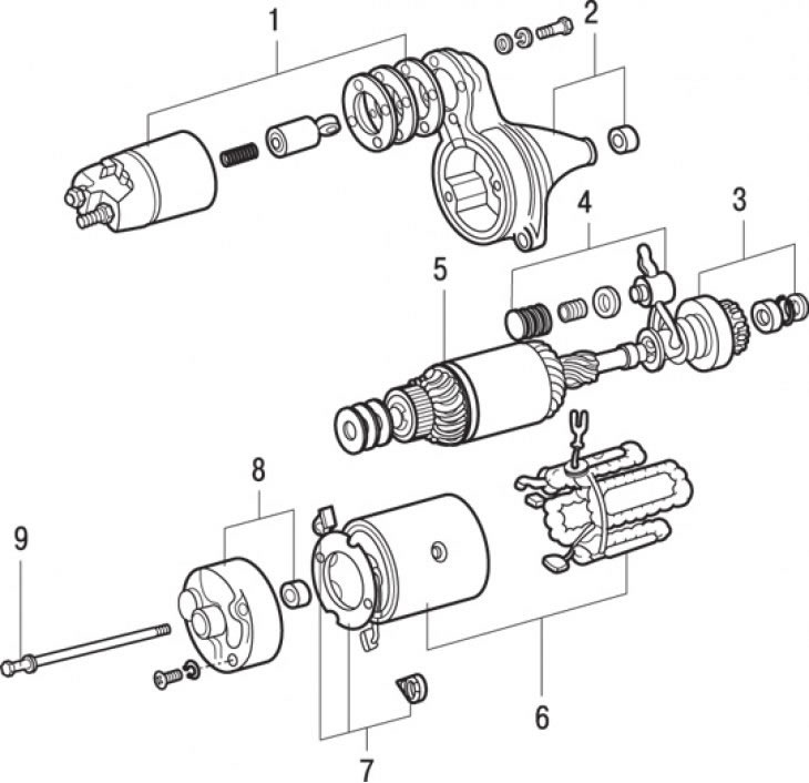
Pic. 13.18. The main elements of the starter: 1 - traction relay and shims; 2 – a forward cover of a starter and the plug of the bearing; 3 - drive gear assembly with freewheel; 4 – gear drive lever; 5 - anchor; 6 - starter housing and excitation windings; 7 - brush holder; 8 - cover and bushing; 9 - coupling bolt
Remove two or three screws securing the traction relay to the starter drive gear cover. Remove the yoke of the traction relay and reinstall the shims, having previously marked their number and location (pic. 13.18). Reinstall the spring.
Unhook the anchor of the traction relay from the gear drive lever.
Remove the commutator brushes and brush holder plate.
Carefully remove the starter housing from the anchor. Hold the anchor - the lever springs and washers may fall out.
Remove the drive lever from the freewheel.
Remove the anchor assembly with the clutch and gear from the front cover of the starter.
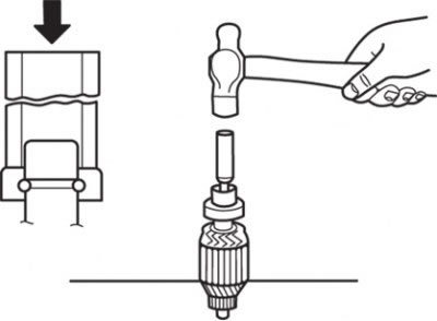
Pic. 13.19. Removing the drive gear assembly with the freewheel
To remove the pinion and freewheel assembly from the anchor, secure the anchor in a vise through two pieces of wood. Using a hammer and a piece of pipe, move the thrust ring towards the gear until the retaining ring is accessible (pic. 13.19). Remove snap ring, thrust ring, starter gear with freewheel.
Examination
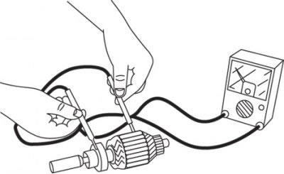
Pic. 13.20. Using an ohmmeter to check the conductivity between the collector lamellas and the core of the rotor winding
Connect an ohmmeter to the collector blades and the rotor winding core and check that there is no conduction between them (pic. 13.20). If there is continuity, replace the rotor.
Check the rotor winding with a special tool. If there is a short circuit in the rotor winding, replace the rotor. If the steel plate brought to the core of the winding vibrates when the core is turned, then there is a short circuit in the winding.
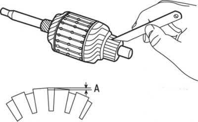
Pic. 13.21. Collector groove cleaning: A=0.5–0.8 mm
Check the manifold for signs of burnout and other defects. Sometimes the collector can be repaired by turning it, but this work should be done by an experienced craftsman. Using a sharpened hacksaw blade or other suitable tool, remove carbon deposits and other contaminants from the grooves between the collector lamellas. The cutting depth of the collector grooves must not exceed that indicated in fig. 13.21.
Connect an ohmmeter between the lamellas of the rotor commutator and check the conductivity in the rotor winding. If there is no conductivity, then there is a break. Replace rotor.
If necessary, the armature bearing bushings can be removed from the covers and replaced with new ones. Before installing the bushings, it is recommended to soak them in engine oil.
Check for visible damage on the parts of the traction relay and clean the rust off the relay armature.
Check the freewheel gear and teeth for wear and damage, replace the freewheel if necessary. Check the flywheel ring gear for damage.
While holding the starter shaft stationary, rotate the freewheel gear. It should rotate freely clockwise and lock when turned counterclockwise.
Assembly
Install the gear assembly with the freewheel on the armature shaft. First put the gear and clutch on the shaft, then the thrust ring. Install a new circlip into the groove of the shaft, secure it by pushing the sleeve over the circlip with force using a pair of open-end wrenches, acting as levers.
Install the anchor in the front cover and hook the drive lever on the freewheel. Put the washer and spring on the lever axle and carefully put on the starter housing with windings.
Install the brush holder, shims, manifold cover and tighten the tie bolts.
Hook the plunger and the yoke of the traction relay to the drive lever, install the shims. Wrap and tighten the screws securing the traction relay, do not connect the starter motor power wire yet.
Bench tests
Pic. 13.22. Checking the retracting winding of the starter traction relay
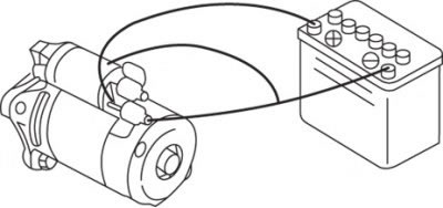
Connect the battery with additional wires to the terminals «S» And «M» and the starter traction relay housing - the starter gear will move forward (pic. 13.22). This check must be carried out as soon as possible (less than 10 s) to prevent burnout of the solenoid coil of the traction relay.
Pic. 13.23. Checking the holding winding of the starter traction relay
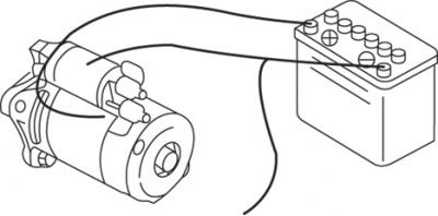
Check the operation of the holding winding of the traction relay as follows. Connect the battery with additional wires to the terminals «S» And «M» and the starter traction relay housing - the starter gear will move forward. Then disconnect the wire from the terminal «M» (pic. 13.23). If the gear remains extended, then everything is in order. If the gear moves back, then the hold circuit is open. Replace magnetic switch.

Pic. 13.24. Traction Relay Solenoid Return Test
Check the return of the traction relay solenoid by connecting the positive terminal of the battery to the terminal «M», and negative - with the housing of the traction relay (pic. 13.24). Pull out the gear and then release it. If the gear quickly returns to its original position, then everything is in order. Otherwise, replace the traction relay solenoid.
If the result of any of these tests is unsatisfactory, replace the traction relay. If all tests are positive, measure the starter gear play as follows.
Connect the negative terminal of the battery to the traction relay housing, and the positive terminal to the terminal «S».
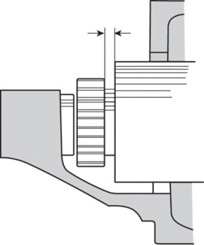
Pic. 13.25. Place for measuring the clearance between the gear and the stopper
Use a feeler gauge to check the clearance between the gear and stopper (gear clearance) (pic. 13.25). If the gear clearance is not as required, adjust it by adding or removing shims between the traction relay and the front cover.
If the traction relay is in good condition, and the gear clearance is as required, connect the power wire of the starter motor to the terminal «M» traction relay and secure it with a nut.
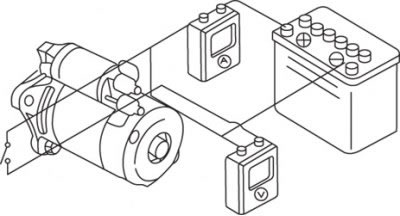
Pic. 13.26. Connection diagram for measuring the current drawn by the starter in no-load operation
Measure the no-load current of the electric motor, for which assemble the circuit, as shown in fig. 13.26, and secure the motor in a vise.
At a voltage of 11.5 V, the current consumption must not exceed 60 A, and the armature speed must be at least 6500 min-1. Do not leave the motor running for a long time at this speed.