
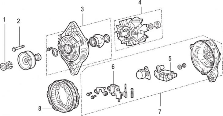
Pic. 13.10. Generator: 1 - nut and washer for fastening the pulley; 2 - screw; 3 - front cover (drive side), bearing and restrictive washer; 4 - rotor and rear bearing; 5 - rectifier; 6 - plate of voltage regulator and brush holders; 7 - back cover with bearing housing; 8 - stator
Loosen the pulley nut and remove the washer (pic. 13.10). While loosening the nut to secure the pulley from turning, squeeze the old drive belt with the bracket.
Remove the pulley, impeller (if the impeller is mounted separately on the shaft), spacer and cup washer.
Turn out three screws of fastening of a back cover of the generator.
Using a 200W soldering iron, heat the back cover with the bearing housing for 3-4 minutes or blow hot air for a longer time (see fig. 13.7). In conclusion, it is necessary to heat the bearing housing to a temperature of 50–60°C without heating other parts.
While the back cover is still warm, remove the front cover with the rotor by inserting a screwdriver blade between the front cover and the stator core. Be careful not to damage the stator windings.
Lightly tap the rotor out of the front bearing.
Loosen the outlet fixing nut «IN» and remove the puck. Turn out from a back cover three screws of fastening of the rectifier, a regulator plate and a brush holder. Remove the stator, rectifier and other parts from the cover.
If electrical testing is to be carried out on the stator or rectifier, unsolder the leads and separate them from each other. Mark the location of the pins so as not to mix them up during assembly. Solder quickly so that the rectifier does not fail due to overheating.
Replace commutator brushes.
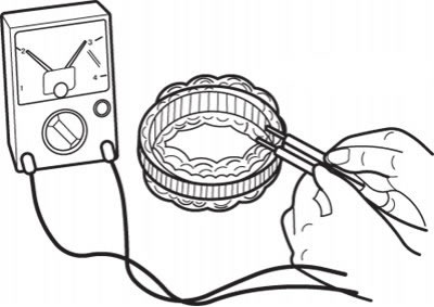
Pic. 13.11. Using an ohmmeter to check the conductivity of the stator windings
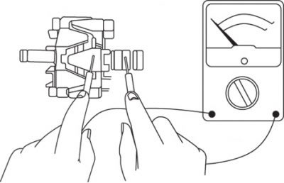
Using an ohmmeter or a 12 V lamp connected in series with the power supply, check the stator windings for open circuits (pic. 13.11). There must be continuity between any pair of leads.
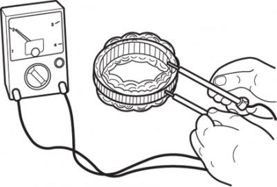
Pic. 13.12. Using an ohmmeter to check continuity between coil and stator core
Check the short circuit of the stator coil to the core. Make sure there is no conduction between the coil and the core, otherwise replace the stator (pic. 13.12).
Check the alternator rotor for damage, especially carefully inspect the collector slip rings. Slight burn marks can be removed by sanding with fine-grained sandpaper, then wipe with a soft cloth lightly dampened with solvent. A badly worn rotor must be replaced.
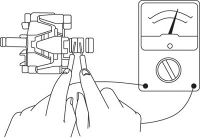
Pic. 13.13. Using an ohmmeter to test for continuity between rotor slip rings
Check the rotor coil. Make sure there is continuity between the slip rings (pic. 13.13). If the resistance is too low, then there is a short circuit in the coil. If there is no continuity or there is a short circuit, replace the rotor.
Pic. 13.14. Using an ohmmeter to check continuity between the slip ring of the rotor and the armature
Check the short circuit of the rotor coil to the armature. Make sure there is no continuity between slip ring and rotor armature (pic. 13.14). If there is continuity, replace the rotor.
Check for free rotation and play in the rotor bearings. If the condition of the bearings is in doubt, replace them. Make sure the rotor bearing is installed correctly on the manifold side (the groove for the retaining ring must be directed towards the slip rings).
Test the continuity of the three diodes by connecting an ohmmeter probe to both ends of each diode. Conductivity should only be in one direction.
If conductivity is found in two directions, then the diode is broken, the rectifier must be replaced.
Assembling the generator should begin with soldering the terminals of the regulator plate, stator and rectifier.
Install the soldered parts in the back cover and secure with screws by installing the washer and tightening the output fixing nut «IN».
Carefully press the brushes in, fix their position with a thin rod or drill, inserting it through the hole in the back cover. The new brushes have special holes into which the retainer enters.
Make sure the rear bearing circlip is in the bearing groove (see fig. 13.9). Heat the rear bearing cap in the same way as when removing it and install the rotor.
Install the belleville washer onto the rotor shaft, making sure it is oriented correctly.
Place the front cover over the rotor and lightly push it into place. Screw in the three screws securing the covers.
Install the second cup washer, spacer, impeller and pulley. Brace the drive belt, install the washer and screw on the nut.
Pull out the retainer holding the brushes in the retracted position, then install the alternator on the vehicle.