MazBook.ru
English Русский
Български
Беларускі
Український
Српски
Hrvatski
Română
Polski
Slovenský
Magyar
• Bookmark • Sitemap • Contacts •   
Cars Opel Cars Ford Cars Volkswagen Cars Audi Cars Kia Cars Renault Cars Peugeot


Familia Capella Mazda3 Mazda6 CX-? Others Articles
Mazda 121 (3) (1996-2003) Mazda BT-50 (1) (2006-2011)

Removal, installation and testing of the clutch (Mazda 121 (3))

  • Home
  • Mazda
  • 121 JASM (1996-2003)
  • Transmission
  • Clutch
  • Removal, installation and testing of the clutch
0
Contents: Removal ⇓ Examination ⇓ Installation ⇓

Removal


Remove the gearbox.

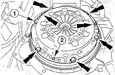
Loosen the mounting bolts (1) (6 pcs.) of the clutch pressure plate one by one by 1-1.5 turns at a…


Loosen the mounting bolts (1) (6 pcs.) of the clutch pressure plate one by one by 1-1.5 turns at a time until the pressure plate is released. To prevent the flywheel from turning when unscrewing the bolts, secure it with a rod or screwdriver.

Caution: If you unscrew the bolts immediately, you may damage the diaphragm spring and the guide pins (2) between the pressure plate and the flywheel.


Finally, completely unscrew the bolts.

Remove the pressure and driven clutch discs.

Attention: The discs must not fall when removed, otherwise jerking and difficulty engaging the clutch may occur after installation.


Clean the flywheel with a rag soaked in gasoline.

Examination


Check the clutch pressure plate for signs of burning and deep scratches and replace it if necessary.

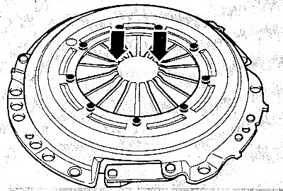
Check the diaphragm spring for damage (arrows).

Check the spring connections between the pressure plate and the cover for cracks, the fastening of…


Check the spring connections between the pressure plate and the cover for cracks, the fastening of the rivets and the tightness of the fit. Replace the disk with damaged or loose rivets.


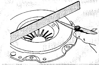
Check the working surface of the pressure plate for scratches, traces of burning and wear. Disks…


Check the working surface of the pressure plate for scratches, traces of burning and wear. Disks that have concavities up to 0.3 mm deep can be used further. Checking is done with a ruler and flat feeler gauges.

Check the flywheel for signs of overheating and pitting.

Treat the clutch pressure plate and flywheel with the finest sandpaper.

An oily or damaged driven disk must be replaced.

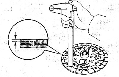
Measure the thickness of the working lining of the driven clutch disc using a caliper. The distance…


Measure the thickness of the working lining of the driven clutch disc using a caliper. The distance to the rivet heads should be at least 0.3 mm. Otherwise, the driven disc must be replaced. The same applies to damaged linings.

The driven clutch disc can be checked for runout in the workshop. Lateral runout should not exceed 0.25 mm.


Note: This check is only necessary if an old driven disc is to be installed and there were previous problems with the clutch operation.


Check the release bearing in the gearbox housing. There should be no visible signs of deformation. Turn the bearing by hand. It should not stick. If the bearing makes noise when disengaging the clutch, it also needs to be replaced.

Installation


Attention: Before installing a new clutch, you must wash off the protective varnish with solvent from the working surface of the pressure plate, and also wipe the flywheel.


Check the three centering pins on the flywheel for tightness.

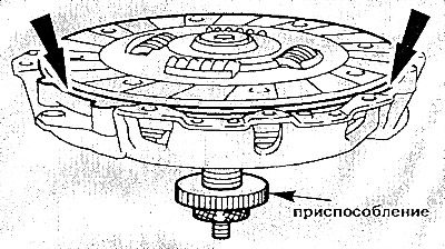
Roughly center the driven disk in the middle of the pressure plate. However, it is better to do…


Roughly center the driven disk in the middle of the pressure plate. However, it is better to do this with a special rod or an old primary shaft of the gearbox.

In specialized workshops, a special device is used. If the driven disk is not centered, it will be impossible to insert the primary shaft of the gearbox later.

Install the pressure plate with the driven plate centered onto the corresponding flywheel mounting pins.

Insert the clutch pressure plate mounting bolts and screw them in by hand, then tighten them crosswise by 1-1.5 turns until the pressure plate is tightened.


Caution: Make sure that the pressure plate is pulled evenly and without distortion toward the flywheel when tightening the bolts. The tightening torque of the bolts is 30 Nm.


Pull out the centering rod.
If used, remove the flywheel locking device.


If used, remove the flywheel locking device.

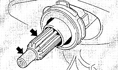
Clean the gearbox input shaft splines and lightly lubricate them with molybdenum-based grease. Do not use too much grease or it will be squeezed out onto the clutch working surfaces, causing the clutch to slip.

Install the gearbox.
This article is available at: russian, bulgarian, belarusian, ukrainian, serbian, croatian, romanian, polish, slovak, hungarian
This text was checked by: Evgeny Mereshnikov
Share with friends on social networks:

Previous
Mazda 121 (3) » Clutch
Next

Clutch — design description
Bleeding the Clutch Hydraulic Drive
Removal, installation and checking the release bearing and slave…
Diagnosing Clutch Faults
More articles on repairing other Mazda models
Detailed technical specifications of the clutch Mazda Familia 5 (1985-1989)
Clutch — description and testing Mazda Capella 6 (1997-2005, petrol)
General information about the clutch Mazda3 BK (2003-2009)
General information about the clutch Mazda6 GG (2002-2008)
Clutch Pedal Position Sensor Mazda CX-5KE (2012-2017)
Link in different formats to this article
Comments and feedback from visitors
No comments yet


How much will 44 + 45 ?


Mazda BT-50 (1) (2006-2011) 
  • General information
  • Introduction to guide
  • User manual
  • Maintenance
  • Power unit
  • Engine repair (diesel)
  • Cooling and lubrication system
  • Fuel injection system
  • Intake and exhaust system
  • Engine electrical equipment
  • Transmission
  • Clutch
  • Mechanical gearbox
  • All-wheel drive system
  • Transfer case and gearboxes
  • Chassis
  • Front suspension
  • Rear suspension
  • Steering
  • Brake system
  • Body
  • Exterior (external elements)
  • Interior (internal elements)
  • Heating and air conditioning
  • Security system SRS
  • Electrical equipment
  • Equipment and devices
  • Electrical circuits
Mazda 121 (3) (1996-2003) 
  • General information
  • User manual
  • Maintenance
  • Power unit
  • Petrol engine 1.3 l
  • Petrol engine 1.25/1.4 l
  • Diesel engine
  • Lubrication system
  • Cooling system
  • Ignition system
  • Supply system
  • Fuel injection (gasoline)
  • Fuel injection (diesel)
  • Exhaust system
  • Transmission
  • Clutch
  • Car gearbox
  • Chassis
  • Front suspension
  • Rear suspension
  • Steering
  • Brake system
  • Wheels and tires
  • Body
  • Exterior (external elements)
  • Interior (internal elements)
  • Doors, windows and locks
  • Heating system
  • Electrical equipment
  • Troubleshooting
  • Equipment and devices
  • Lighting system
  • Power devices
  • Electrical circuits
MazBook.ru © 2018–2026 · Mobile version · Articles and news · Sitemap: EN BG BY UA RS HR RO PL SK HU · Feedback · Site search · Add to bookmarks Familia 5 (BF) · Familia 6 (BG) · Capella 3 (GC) · Capella 3 and 4 (GC) · Capella 4 (GD) · Capella 5 (GE) · Capella 6 (GF) · Mazda3 BK · Mazda6 GG · CX-5KE · Mazda 121 (3) · Mazda BT-50 (1) ·
By continuing to use the site, you agree to the use of cookies 🔐