


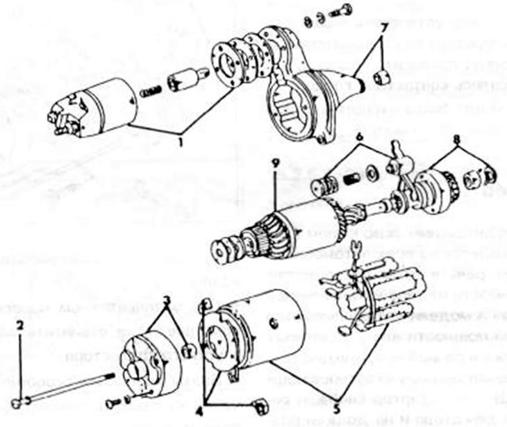
Figure 255. Starter assembly drawing 1. Pull-in winding switch; 2. Expansion bolt; 3. Back cover; 4. Brush holder crossbar; 5. Starter housing; 6. Switch lever; 7. Generator front cover; 8. Starter gears; 9. Anchor
- Disconnect the connecting cable from the magnetic switch terminal.
- Loosen both switch bolts and remove the switch. Watch the insert washers.
- Remove both tie bolts (2) from the rear of the starter and remove the generator cover together with the armature from the starter housing.
- Remove the starter lever (loosen the bolts) and remove the anchor from the generator cover on the drive side. In this case, pay attention to the principle of installing the lever in order to later return the parts to their original position.
- Remove the brushes from the holders and remove the brush holder crossbar.
- Hit the thrust ring at the end of the anchor shaft with a chisel and remove the safety ring sitting on it (figure 256). Remove the burr from the end of the anchor shaft and pull the engine off the shaft.
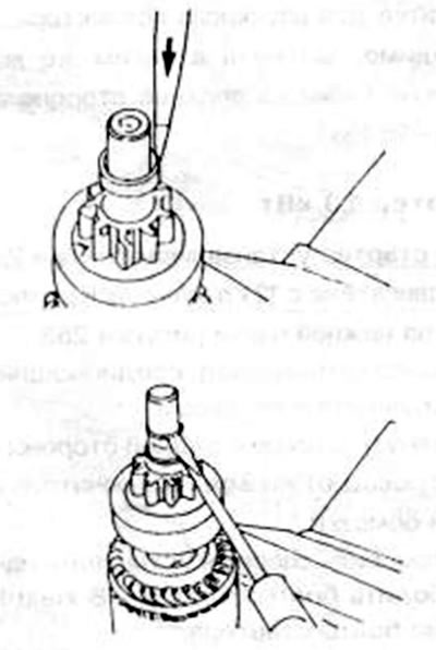
Figure 256. Driving in the connecting ring with a chisel (in the top picture) and removing the safety clip (in the picture below).