
MazBook.ru
English Русский
Български
Беларускі
Український
Српски
Hrvatski
Română
Polski
Slovenský
Magyar
• Bookmark • Sitemap • Contacts •   
Cars Opel Cars Ford Cars Volkswagen Cars Audi Cars Kia Cars Renault Cars Peugeot


Familia Capella Mazda3 Mazda6 CX-? Others Articles
Capella 3 (1982-1992, petrol) Capella 3 and 4 (1982-1992) Capella 4 (1987-1992) Capella 5 (1991-1997) Capella 6 (1997-2005, petrol)

Checking the details (Mazda Capella GD)

  • Home
  • Mazda Capella
  • Capella GD (1987-1992)
  • Electrical equipment
  • Equipment and devices
  • Checking the details
0
Contents: 18.2.5.1. Carbon brushes and brush…⇓ 18.2.5.2. Rotor ⇓ 18.2.5.3. Starter ⇓ 18.2.5.4. Diodes ⇓

18.2.5.1. Carbon brushes and brush holder crossbar


Check the carbon brushes for good contact with the slip rings. Check the mobility of the carbon in the guides and, if necessary, clean the brush holder with Tri.
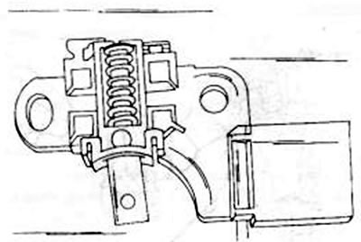
Figure 247. Carbon brushes are soldered in the indicated places.

Figure 247. Carbon brushes are soldered in the indicated places.


Measure the length of the protruding part of the carbon brush. If the wear line is reached, the brushes must be replaced. To do this, the old brushes need to be removed and the new ones soldered on.

The brush wear line should protrude 2-3 mm from the end of the brush holder. Hold the brush in this position and solder the brush wire (core) with good zinc solder.

18.2.5.2. Rotor


If the contact rings are dirty or worn, wipe them with a cloth soaked in Tri. Any scratches can be polished with a fine lubricating paste.

To test the insulation, one tip of the ohmmeter is placed on the rotor core and the other on the slip ring. The ohmmeter reading should be continuous (figure 248). If this does not happen, the entire rotor must be replaced.
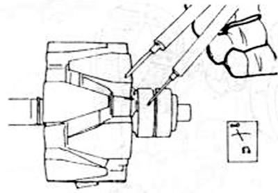


Figure 248. Checking the rotor for short circuit to the housing.

Figure 248. Checking the rotor for short circuit to the housing.


To check the rotor winding for current flow, both tips of the ohmmeter must be placed on the contact ring. If the reading is not within 2.0-6.0 ohms, the rotor needs to be replaced (figure 249).
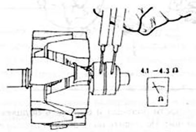
Figure 249. Checking the rotor for current interruption

Figure 249. Checking the rotor for current interruption


18.2.5.3. Starter


Short circuits occur in most cases due to strong heating of damaged areas and are detected during inspection. You can also place the tip of the ohmmeter on the end of the phase and the other tip on the stator housing. The device must give continuous readings (figure 250). Otherwise, the stator needs to be replaced. To test the stator for current interruption, you need to connect the three stator wires to each other one by one.
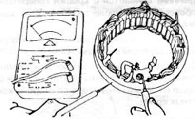


Figure 250. Stator short circuit test to housing.

Figure 250. Stator short circuit test to housing.


If there is no reading, the current flow is interrupted (figure 251).
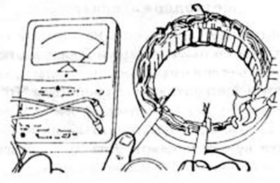
Figure 251. Stator current interruption monitoring

Figure 251. Stator current interruption monitoring


18.2.5.4. Diodes


Accurate testing of diodes for the presence of conduction voltage and the establishment of reverse current can only be carried out using a special test device.
This article is available at: russian, bulgarian, belarusian, ukrainian, serbian, croatian, romanian, polish, slovak, hungarian
This text was checked by: Georgy Afanasyev
Share with friends on social networks:

Previous
Capella 4 » Equipment and devices
Next

Disassembling the generator
Removal and installation the battery
Checking the installed brushless alternator
Safety precautions when working on a charging current installation
Rechargeable battery
Assembling the generator
Starter — general information
Removal and installation the starter
Disassembling the starter
Checking the starter parts
More articles on repairing other Mazda models
Checking electrical characteristics Mazda Familia 5 (1985-1989)
Checking the operation of the parking brake Mazda3 BK (2003-2009)
Checking the operation of the parking brake Mazda6 GG (2002-2008)
Checking the oil Mazda CX-5KE (2012-2017)
Checking and adjusting valve clearance Mazda 121 (3) (1996-2003)
Link in different formats to this article
Comments and feedback from visitors
No comments yet


How much will 28 + 36 ?


Capella 6 (1997-2005, petrol) 
  • General information
  • Introduction to guide
  • User manual
  • Troubleshooting
  • Maintenance
  • Power unit
  • 4-cylinder engines
  • 6-cylinder engines
  • Engine overhaul
  • Cooling and ventilation
  • Power and exhaust systems
  • Engine electrics
  • Control system
  • Transmission
  • Mechanical gearbox
  • Automatic gearbox
  • Clutch and drive shafts
  • Chassis
  • Brake system
  • Car suspension
  • Steering
  • Body
  • Exterior (external elements)
  • Interior (internal elements)
  • Doors, windows and locks
  • Electrical equipment
  • Equipment and devices
  • Electrical circuits
Capella 5 (1991-1997) 
  • General information
  • User manual
  • Maintenance
  • Helpful hints
  • Power unit
  • Petrol engines 1.6 and 1.8
  • Petrol engines 2.0
  • 2.5 petrol engines
  • Overhaul engines 1.6 and 1.8
  • Overhaul engines 2.0 and 2.5
  • Diesel engine 2.0
  • Engine electrics
  • Cooling system
  • Air conditioner
  • Carburetor Nikki 30/34
  • Power system (1.6 and 1.8)
  • Power system (2.0 and 2.5)
  • Control system
  • Transmission
  • Mechanical gearbox
  • Automatic gearbox
  • Clutch and axles
  • Chassis
  • Brake system
  • Suspension and wheels
  • Steering
  • Body
  • Exterior (external elements)
  • Interior (internal elements)
  • Doors and windows
  • Electrical equipment
  • Equipment and devices
  • Electrical circuits
Capella 4 (1987-1992) 
  • General information
  • Introduction to manual
  • Vehicle specifications
  • Power unit
  • Engine repair
  • Lubrication system
  • Cooling system
  • Fuel system (carburetor)
  • Fuel injection (FE)
  • Fuel injection (DOHC)
  • Fuel system (diesel)
  • Ignition system
  • Transmission
  • Clutch
  • Gearbox
  • Drive shafts
  • Chassis
  • Front suspension
  • Rear suspension
  • Steering system
  • Brake system
  • Electrical equipment
  • Equipment and devices
  • Electrical circuits
Capella 3 and 4 (1982-1992) 
  • General information
  • User manual
  • Maintenance
  • Power unit
  • Gasoline engine
  • Engine overhaul (gasoline)
  • Diesel engine
  • Cooling and heating
  • Supply system
  • Ignition system
  • Emission reduction
  • Transmission
  • Clutch
  • Mechanical gearbox
  • Automatic gearbox
  • Drive shafts
  • Chassis
  • Brake system
  • Suspension and wheels
  • Steering
  • Body
  • Exterior (external elements)
  • Interior (internal elements)
  • Electrical equipment
  • Equipment and devices
  • Power devices
  • Electrical circuits
Capella 3 (1982-1992, petrol) 
  • General information
  • User manual
  • Maintenance
  • Troubleshooting
  • Late models
  • Power unit
  • Engine in car
  • Engine overhaul
  • Cooling and heating system
  • Fuel and exhaust system
  • Engine electrical system
  • Emission control system
  • Transmission
  • Mechanical gearbox
  • Automatic gearbox
  • Clutch and drive shafts
  • Chassis
  • Brake system
  • Suspension and wheels
  • Steering
  • Body
  • Exterior (external elements)
  • Interior (internal elements)
  • Electrical equipment
  • Equipment and devices
  • Lighting and lamps
  • Electrical circuits
MazBook.ru © 2018–2026 · Mobile version · Articles and news · Sitemap: EN BG BY UA RS HR RO PL SK HU · Feedback · Site search · Add to bookmarks Familia 5 (BF) · Familia 6 (BG) · Capella 3 (GC) · Capella 3 and 4 (GC) · Capella 4 (GD) · Capella 5 (GE) · Capella 6 (GF) · Mazda3 BK · Mazda6 GG · CX-5KE · Mazda 121 (3) · Mazda BT-50 (1) ·
By continuing to use the site, you agree to the use of cookies 🔐