


Contents: 18.3.3.1 Brush mechanism ⇓ 18.3.3.2. Collector ⇓ 18.3.3.3. Pole coils ⇓ 18.3.3.4. Anchor ⇓ 18.3.3.5. Bearing ⇓ 18.3.3.6. Starter drive ⇓ 18.3.3.7. Pull-in winding switch ⇓
18.3.3.1 Brush mechanism
The brushes must be longer than 17.0 mm. Check that the brushes move easily along the guides during installation by gently pulling the connecting cord back and forth. If necessary, wipe the sides of the brushes with a rag soaked in gasoline or smooth them with a file. If necessary, replace the brushes by unsoldering or soldering them at the connection points of the excitation coil.
18.3.3.2. Collector
A good collector should be smooth across the entire surface and should not have any scars or burnt areas. The collector must be wiped with a rag soaked in gasoline while simultaneously rotating the anchor. If this does not help, you can also wipe it with a piece of sandpaper, but do not use any lubricating pastes.
To restore a heavily worn commutator, it can be clamped on a lathe and a layer of metal can be removed at a high speed. Do not remove more metal than necessary.
But do not go beyond the minimum permissible diameter:
— Starter 0.85 and 0.95 kW = 31.0 mm
— Starter 1.4 kW = 28.8 mm
- Diesel engine = 34.0 mm.
Finally, use a saw to cut step slots to a depth of 0.5–0.8 mm, as shown in Figure 257. After this, polish the manifold with sandpaper until it shines. The step slots between the collector segments must also be cut to size if they are only 0.2 mm deep.
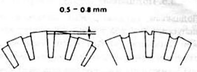
Figure 257. Correct (left) and incorrect (right) cutting of the mica layer between collector segments
(The article is copied from the website: MazBook)
Most often, defects in the collector occur due to a short circuit in the anchor. The most obvious sign of this is a burnt commutator winding.
18.3.3.3. Pole coils
Pole coils are best tested with an ammeter inserted between the coil connections and the case when the battery is connected (figure 258). If there is a reading, the coil is shorted to the housing. For the second check, the ammeter is applied to both brushes (figure 259).
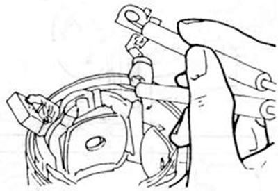
Figure 258. Checking the excitation coil for a short circuit to the housing
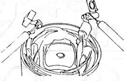
Figure 259. Checking the excitation coil for overcurrent
If there is no reading, the electrical target is interrupted. In both cases, you will need to install a new starter housing or replace the pole coil. The pole shoe bolts should come free with a tap from a screwdriver as they are very tightly held.
18.3.3.4. Anchor
To check the armature windings, an armature testing device is used. called a buzzer. If this device is not available, you can test the old anchor by first installing the new anchor.
Never attempt to straighten a bent armature shaft or machine the core.
Caution! If the starter pinion is replaced due to damaged teeth, the flywheel ring gear should be inspected immediately, as it may also be damaged.
18.3.3.5. Bearing
A bearing that is damaged to the point that it allows lateral play in the armature shaft must be replaced. To do this, it is best to measure the outer diameter of the anchor and the inner diameter of the sleeve. If the difference between them is more than 0.2 mm, you need to press out the old bushing and press in the new one, and turn the bushing until a gap of 0.035-0.08 mm is obtained using the armature shaft.
18.3.3.6. Starter drive
Check that the starter gear teeth are in good condition. The gear should move easily along the helical thread of the armature shaft. Free movement is allowed only in one direction, while in the other it is locked. If necessary, you need to replace the complete drive, but before ordering, count the number of gear teeth.
18.3.3.7. Pull-in winding switch
The pull-in winding switch cannot be repaired. To test the switch coil, a 12-volt battery is connected to both terminals shown in Figure 260. There should be a current reading.
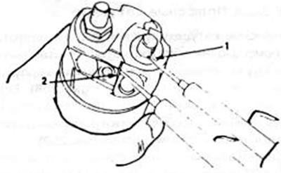
Figure 260. Checking the switch pull-in winding using an ohmmeter. It is applied to terminals (1) and (2) (see text).
This check shows that the traction reel is OK. To check the holding coil, the ends of the test device must be connected between the left terminal and the switch housing. The presence of current indicates that the holding coil is OK.