
Valve clearances
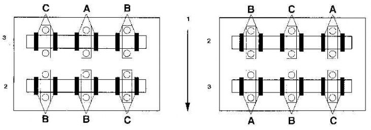
1. Forward
2. Inlet valves
3. Exhaust valves
4. Front cylinder block
5. Rear cylinder block
1. Disconnect the negative battery cable.
2. Remove the valve cover.
3. Set the piston of cylinder N1 to the TDC position at the time of the compression stroke.
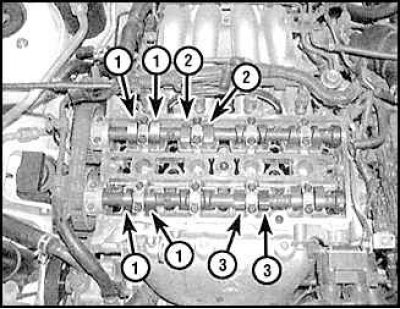
4. On models with a 4-cylinder engine, set the piston of the N1 cylinder to the TDC position at the time of the compression stroke and measure the clearances of the indicated valves.
5. On a 6-cylinder engine, with the N1 piston at TDC on the compression stroke, measure the clearances of the valves marked A, rotate the engine 240°clockwise and measure the clearances of the valves marked B, then turn the engine crankshaft another 240°and measure the valve clearances marked C (see fig. Valve clearances).
6. Measure the clearance between the valve lifter and the camshaft lobe using a feeler gauge set - if the clearance is correct, friction should be felt when the feeler gauge is removed.
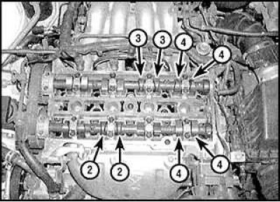
7. On four-cylinder models, with the N4 cylinder piston at TDC on the compression stroke, measure the N2 and 4 exhaust valve clearances and the N3 and 4 intake valve clearances.
8. Valve clearances can be adjusted by removing the timing belt or without removing it.
Adjustment operation with removal of the timing belt
1. Remove the toothed belt and camshafts.
2. Remove washers from valve lifters requiring adjustment and measure their thickness.
3. Install new washers of the required thickness, then install the camshafts and bearing caps. Tighten the fixing bolts to the required tightening torque.
4. Recheck valve clearances.
Adjustment operation without removing the timing belt
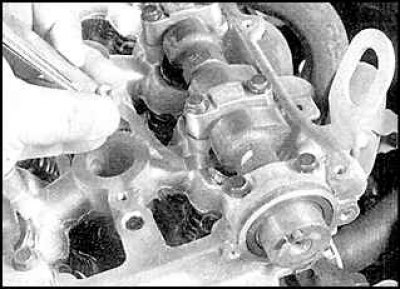
1. Rotate the crankshaft so that the cam above the valve requiring adjustment is up.
2. Rotate the valve lifter with the slot towards the spark plug. On a 6-cylinder engine, unscrew the inner bolts of the extreme caps of the camshaft bearings (excluding large thrust bearing caps). On a 4-cylinder engine, unscrew the inner bolts of the bearing caps closest to the adjustable valve. Install the clamp bar on the bearing caps and secure it with the long bolts. Tighten the clamp by pushing the valve lifter down and remove the shim using a small screwdriver and a magnet or tweezers.
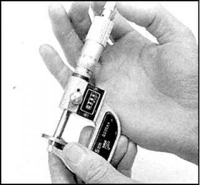
3. Measure the washer thickness with a micrometer.
Calculate the required new washer thickness using the following formula:
H = T + (Z - R)
where T is the thickness of the old washer
H - valve clearance
H - the thickness of the new washer
P - recommended valve clearance
4. Install a new washer and recheck the valve clearance.