
MazBook.ru
English Русский
Български
Беларускі
Український
Српски
Hrvatski
Română
Polski
Slovenský
Magyar
• Bookmark • Sitemap • Contacts •   
Cars Opel Cars Ford Cars Volkswagen Cars Audi Cars Kia Cars Renault Cars Peugeot


Familia Capella Mazda3 Mazda6 CX-? Others Articles
Capella 3 (1982-1992, petrol) Capella 3 and 4 (1982-1992) Capella 4 (1987-1992) Capella 5 (1991-1997) Capella 6 (1997-2005, petrol)

Axle shaft boots — replacement (Mazda Capella GE)

  • Home
  • Mazda Capella
  • Capella GE (1991-1997)
  • Transmission
  • Clutch and axles
  • Axle shaft boots — replacement
0
Contents: Replacement ⇓ Inner CV joint ⇓ Outer CV joint ⇓

Replacement


1. Remove the axle shaft from the vehicle.

2. Clamp the axle shaft in a vice.

Inner CV joint


Tripod type hinge


Removal elements


Removal elements


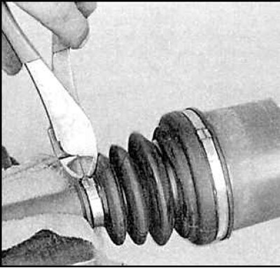
1. Remove the boot mounting clamps.
1. Remove the boot mounting clamps.


2. Move the boot to the side.
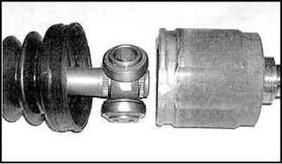
2. Move the boot to the side.


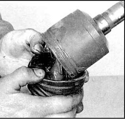
3. Mark the tripod installation position in the housing and remove the housing.


3. Mark the tripod installation position in the housing and remove the housing.


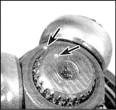
4. Mark the tripod mounting position on the axle shaft (marks are indicated by arrows).
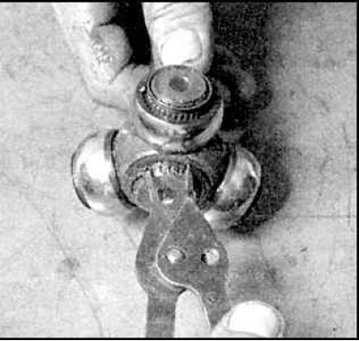
4. Mark the tripod mounting position on the axle shaft (marks are indicated by arrows).


5. Remove the retaining ring from the end of the axle shaft.
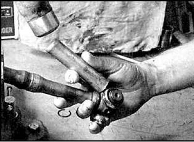
5. Remove the retaining ring from the end of the axle shaft.


6. Knock the tripod off the end of the axle shaft.

Inspection


1. Remove old grease thoroughly.

2. Inspect all hinge components for scratches, corrosion, other signs of wear or damage. Replace the hinge if necessary.


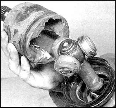
Assembly of elements


Assembly of elements


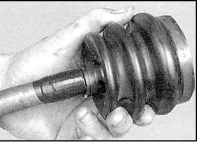
1. Place the boot and clamps on the axle shaft. Wrap the splines with tape before installing the boot.
1. Place the boot and clamps on the axle shaft. Wrap the splines with tape before installing the…


2. Place the tripod on the axle shaft and install the retaining ring. Fill the tripod and hinge housing with grease.

3. Install the cover onto the tripod.
3. Install the cover onto the tripod.


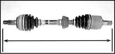
4. Adjust the axle shaft length using the values given below subsection 8.2.


4. Adjust the axle shaft length using the values given below subsection 8.2.


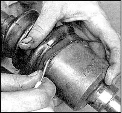
5. Lift the edge of the boot to equalize the pressure inside and outside the boot.
5. Lift the edge of the boot to equalize the pressure inside and outside the boot.


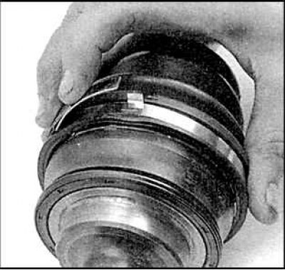
6. After tightening the clamp, bend the end of the clamp.
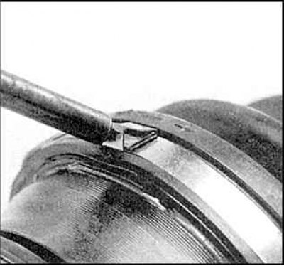
6. After tightening the clamp, bend the end of the clamp.


7. Secure it with the locking tabs.
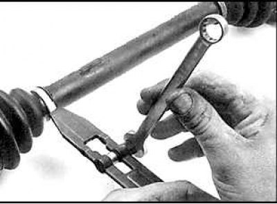
7. Secure it with the locking tabs.


8. To install the band clamp, tighten it using a special tool, turn the tool 90°.
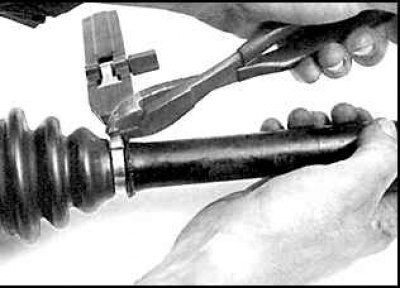


8. To install the band clamp, tighten it using a special tool, turn the tool 90°.


9. Cut off the excess.
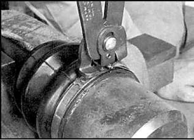
9. Cut off the excess.


10. To install the clamp, you need to use a special tool.

Ball joint


Removal elements


1. Remove the clamps.

2. Move the boot to the side.
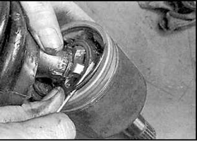
2. Move the boot to the side.


3. Remove the retaining ring from the housing.
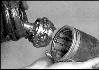
3. Remove the retaining ring from the housing.


4. Remove the casing.
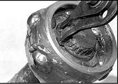


4. Remove the casing.


5. Remove the retaining ring from the end of the axle shaft.

6. Remove the ball cage.
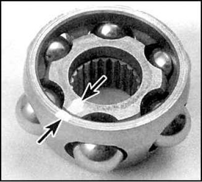
6. Remove the ball cage.


7. Mark the installation position of the inner race track.

8. Carefully remove the balls and peel off the inner track.

Inspection


Inspection


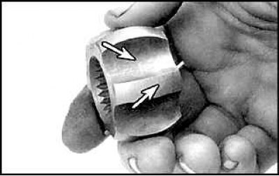
1. Thoroughly clean all components of old grease and inspect the inner race for corrosion, scratches, cracks or other damage.
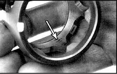


1. Thoroughly clean all components of old grease and inspect the inner race for corrosion,…


2. Inspect the clip for corrosion, scratches, cracks or other damage.

Assembly of elements


1. Place the boot and clamps on the axle shaft.
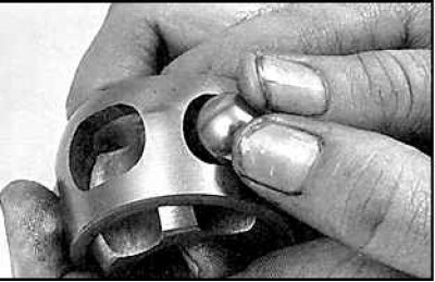
1. Place the boot and clamps on the axle shaft.


2. Insert the inner track and balls into the cage.

3. Fill the ball race with grease.
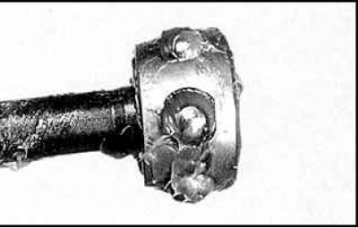
3. Fill the ball race with grease.


4. Install the collar on the axle shaft with the side with the larger diameter facing out.


5. Install the retaining ring to secure the clip.

6. Fill the hinge housing with grease.

7. Install the snap ring into the hinge housing.

8. Install the housing onto the ball race and install the boot in place.

9. Lift the edge of the boot to equalize the pressure inside and outside the boot.

10. Adjust the axle shaft length.

11. Tighten the boot clamps.

All internal hinges


Install a new snap ring onto the end of the axle shaft. Install the axle shaft onto the vehicle.

Outer CV joint


1. Remove the boot clamps and move the boot to the side.

2. Thoroughly clean the joint from old grease using solvent. Wash and dry the joint.
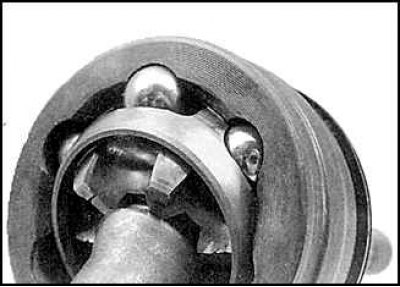
2. Thoroughly clean the joint from old grease using solvent. Wash and dry the joint.


3. Carefully remove old grease and inspect the hinge components for corrosion, damage or wear. If the joint is worn, the axle shaft must be replaced.

4. Replace the outer ball joint boot, removing the inner ball joint and dynamic damper if necessary.

5. Install the new boot onto the joint, fill the boot with grease and tighten the mounting clamps.

6. Install the axle shaft onto the vehicle.
This article is available at: russian, bulgarian, belarusian, ukrainian, serbian, croatian, romanian, polish, slovak, hungarian
This text was checked by: Evgeny Mereshnikov
Share with friends on social networks:

Previous
Capella 5 » Clutch and axles
Next

Intermediate shaft — removal and installation
Axle shafts — removal and installation
Interlock switch
Adjusting the clutch pedal
Release bearing and release bearing fork
More articles on repairing other Mazda models
Shaft parts of 5-speed gearbox type «F» Mazda Familia 5 (1985-1989)
Checking the primary shaft elements Mazda3 BK (2003-2009)
Distributor shaft Mazda6 GG (2002-2008)
Front axle of the car Mazda CX-5KE (2012-2017)
Rear axle shaft — removal Mazda BT-50 (1) (2006-2011)
Link in different formats to this article
Comments and feedback from visitors
No comments yet


How much will 15 + 20 ?


Capella 6 (1997-2005, petrol) 
  • General information
  • Introduction to guide
  • User manual
  • Troubleshooting
  • Maintenance
  • Power unit
  • 4-cylinder engines
  • 6-cylinder engines
  • Engine overhaul
  • Cooling and ventilation
  • Power and exhaust systems
  • Engine electrics
  • Control system
  • Transmission
  • Mechanical gearbox
  • Automatic gearbox
  • Clutch and drive shafts
  • Chassis
  • Brake system
  • Car suspension
  • Steering
  • Body
  • Exterior (external elements)
  • Interior (internal elements)
  • Doors, windows and locks
  • Electrical equipment
  • Equipment and devices
  • Electrical circuits
Capella 5 (1991-1997) 
  • General information
  • User manual
  • Maintenance
  • Helpful hints
  • Power unit
  • Petrol engines 1.6 and 1.8
  • Petrol engines 2.0
  • 2.5 petrol engines
  • Overhaul engines 1.6 and 1.8
  • Overhaul engines 2.0 and 2.5
  • Diesel engine 2.0
  • Engine electrics
  • Cooling system
  • Air conditioner
  • Carburetor Nikki 30/34
  • Power system (1.6 and 1.8)
  • Power system (2.0 and 2.5)
  • Control system
  • Transmission
  • Mechanical gearbox
  • Automatic gearbox
  • Clutch and axles
  • Chassis
  • Brake system
  • Suspension and wheels
  • Steering
  • Body
  • Exterior (external elements)
  • Interior (internal elements)
  • Doors and windows
  • Electrical equipment
  • Equipment and devices
  • Electrical circuits
Capella 4 (1987-1992) 
  • General information
  • Introduction to manual
  • Vehicle specifications
  • Power unit
  • Engine repair
  • Lubrication system
  • Cooling system
  • Fuel system (carburetor)
  • Fuel injection (FE)
  • Fuel injection (DOHC)
  • Fuel system (diesel)
  • Ignition system
  • Transmission
  • Clutch
  • Gearbox
  • Drive shafts
  • Chassis
  • Front suspension
  • Rear suspension
  • Steering system
  • Brake system
  • Electrical equipment
  • Equipment and devices
  • Electrical circuits
Capella 3 and 4 (1982-1992) 
  • General information
  • User manual
  • Maintenance
  • Power unit
  • Gasoline engine
  • Engine overhaul (gasoline)
  • Diesel engine
  • Cooling and heating
  • Supply system
  • Ignition system
  • Emission reduction
  • Transmission
  • Clutch
  • Mechanical gearbox
  • Automatic gearbox
  • Drive shafts
  • Chassis
  • Brake system
  • Suspension and wheels
  • Steering
  • Body
  • Exterior (external elements)
  • Interior (internal elements)
  • Electrical equipment
  • Equipment and devices
  • Power devices
  • Electrical circuits
Capella 3 (1982-1992, petrol) 
  • General information
  • User manual
  • Maintenance
  • Troubleshooting
  • Late models
  • Power unit
  • Engine in car
  • Engine overhaul
  • Cooling and heating system
  • Fuel and exhaust system
  • Engine electrical system
  • Emission control system
  • Transmission
  • Mechanical gearbox
  • Automatic gearbox
  • Clutch and drive shafts
  • Chassis
  • Brake system
  • Suspension and wheels
  • Steering
  • Body
  • Exterior (external elements)
  • Interior (internal elements)
  • Electrical equipment
  • Equipment and devices
  • Lighting and lamps
  • Electrical circuits
MazBook.ru © 2018–2026 · Mobile version · Articles and news · Sitemap: EN BG BY UA RS HR RO PL SK HU · Feedback · Site search · Add to bookmarks Familia 5 (BF) · Familia 6 (BG) · Capella 3 (GC) · Capella 3 and 4 (GC) · Capella 4 (GD) · Capella 5 (GE) · Capella 6 (GF) · Mazda3 BK · Mazda6 GG · CX-5KE · Mazda 121 (3) · Mazda BT-50 (1) ·
By continuing to use the site, you agree to the use of cookies 🔐