
Note 1. If CV joints need to be repaired (usually due to damaged protective covers), carefully study all the details of the upcoming work before starting it. It is more convenient to purchase a restored hinge instead of repair, which will save a lot of time and effort. However, in any case, first find out the cost of spare parts and the possibility of acquiring them, and then proceed with the repair.+
Note 2: Replacement boots may be designed to fit without removing the drive shaft. Buying such covers is a temporary measure. In addition, it is desirable to remove the drive shaft in order to make sure that the constant velocity joint is not dirty. Otherwise, the hinge will quickly fail.
Note 3: In vehicles equipped with ABS, the sensor rings of the system are installed on the outer hinges. Inspect the rings and make sure they are not damaged. Cover rings if necessary.
1. Remove the drive shaft (see paragraph 11).
2. Clamp the drive shaft in a vise with wooden spacers (not to damage the shaft).
Internal hinge and its cover
Three-finger type hinge
Disassembly
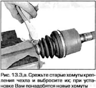
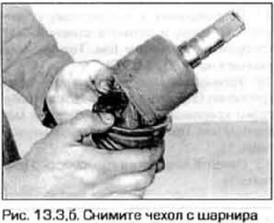
3. Remove boot straps (pic. 13.3, a, b).
 |  |
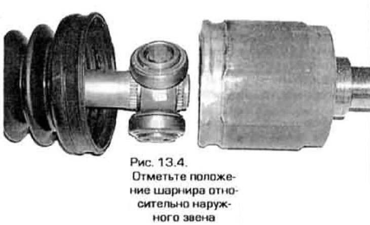
4. Remove the cover from the hinge, then remove the retaining ring and remove the body from the hinge. Before doing this, mark the position of the hinge relative to the body (pic. 13.4).
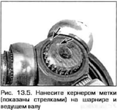
5. Punch marks on pivot and driveshaft to ensure proper assembly (pic. 13.5).
6. Using pliers, remove the circlip from the drive shaft (pic. 13.6).

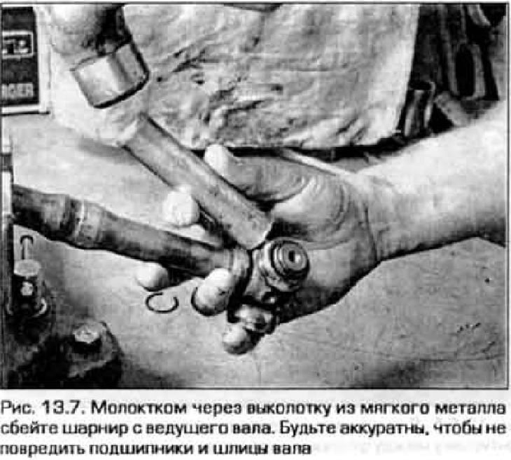
7. Using a hammer and a soft metal drift, knock the joint off the drive shaft (pic. 13.7).
Examination
8. Remove old grease from body and pivot. Disassemble each section of the hinge in turn (do not disassemble the sections at the same time, so as not to mix up the parts) and wash the bearing needles in solvent.
9. Inspect the bearing pins, axles, and outer bearing races for damage or wear. Replace hinge if necessary.
Assembly
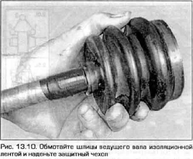
10. Wrap the splines of the input shaft with electrical tape so that they do not damage the cover. Put the clamps and cover on the drive shaft (pic. 13.10).
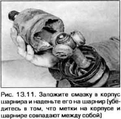
11. Install the joint on the drive shaft (so that the marks made before removing the hinge coincide), then insert the retaining ring. Apply grease to the hinge, the inner surface of the hinge housing and put it in a bag (pic. 13.11).
12. Put the cover on the hinge so that its ends fall into the corresponding grooves.
13. Adjust the length of the hinge according to technical data (fig 13.13).

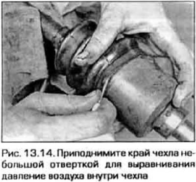
14. Equalize the air pressure inside the case (pic. 13.14).
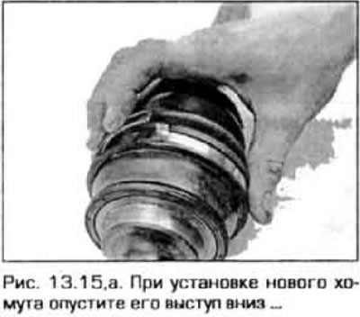
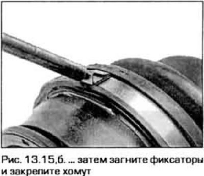
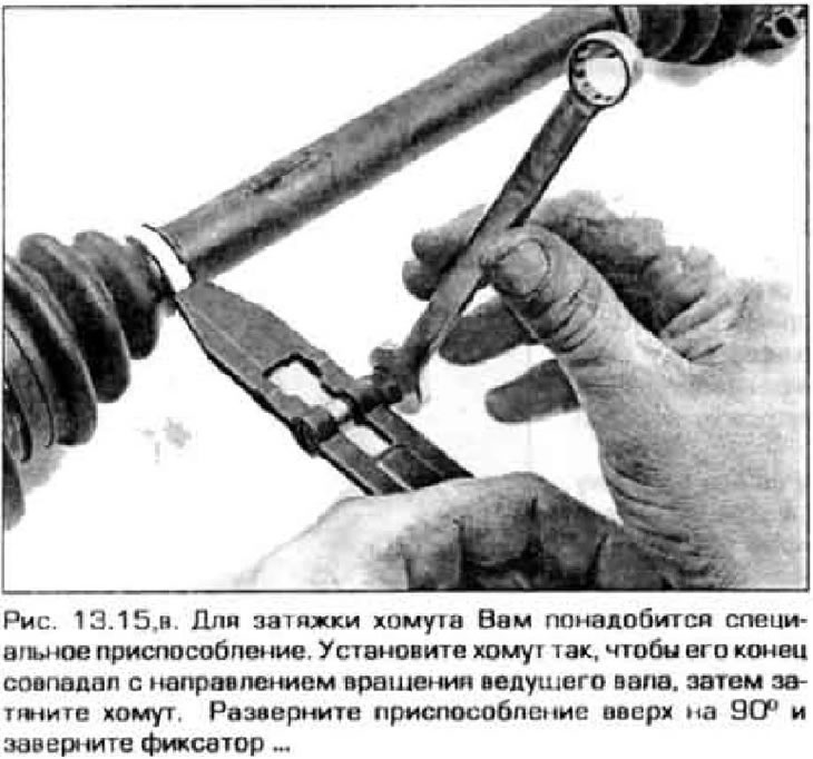
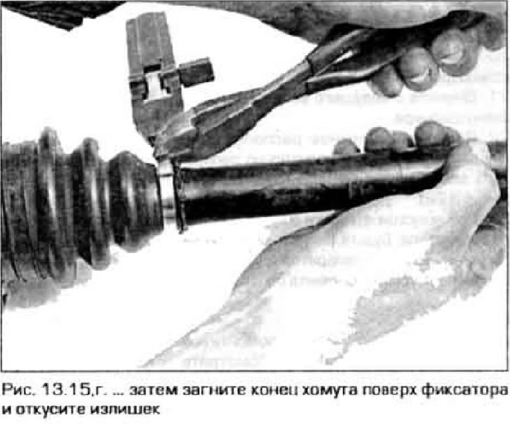
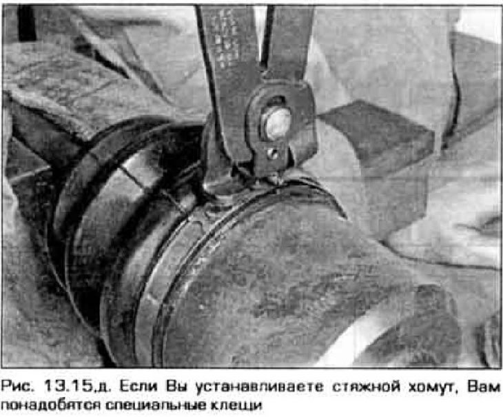
15. Tighten the clamps of the cover (fig 13.15, a-d). Go to step 35.
 |  |
Ball joint
Disassembly
16. Remove boot straps (see Figure 13.3,a) and throw them away.
17. Remove the cover from the hinge.
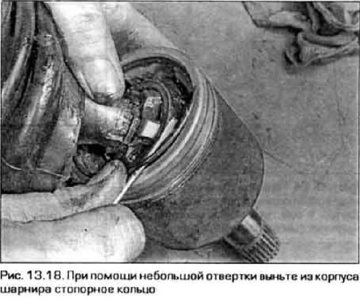
18. Remove the retaining ring from the hinge housing (fig 13.18).
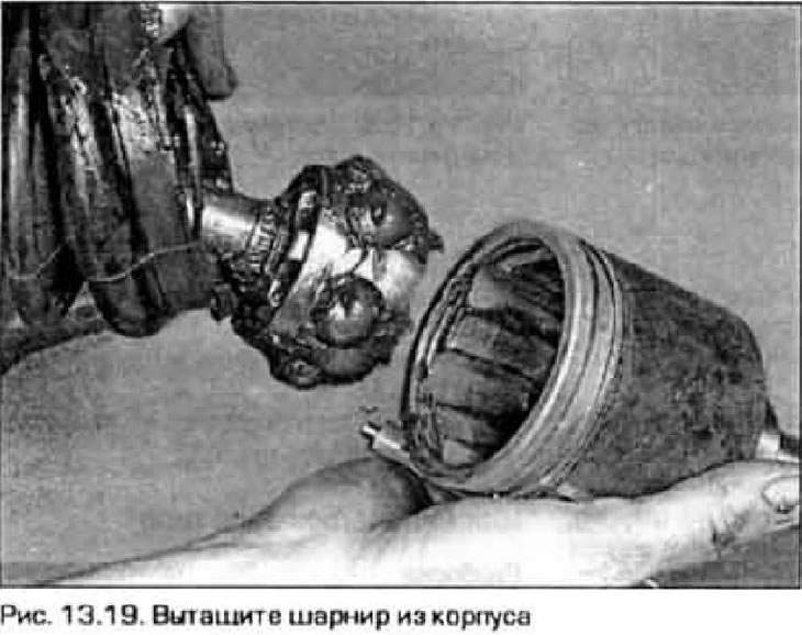
19. Remove the housing from the hinge (pic. 13.19).
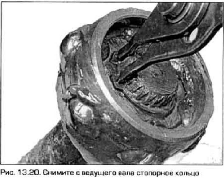
20. Remove the retaining ring from the drive shaft (pic. 13.20).
21. Remove the inner link from the drive shaft.
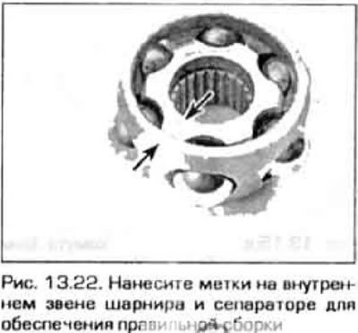
22. Mark the relative position of the inner® «pushing the rings against the cage to ensure proper assembly (pic. 13.22).
23. Using a screwdriver, remove the balls from the separator. Be careful not to damage the balls, cage, or inner pivot link. Remove separator.
Examination
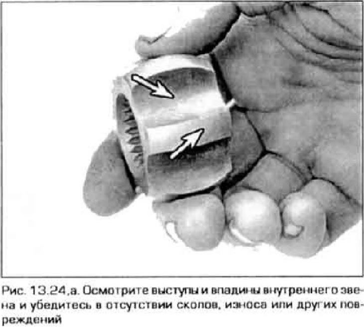
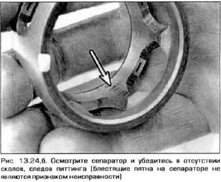
24. Remove old grease and wash all components in solvent Inspect cage and rings for pitting, chipping, wear or damage (pic. 13.24, a, b). Shiny spots on the surfaces are not a sign of their malfunction.
Assembly
25. Wrap the splines of the input shaft with electrical tape so that they do not damage the boot. Put the clamps and cover on the drive shaft, and then remove the insulating tape.
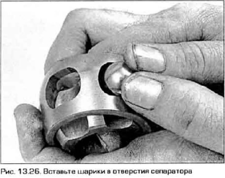
26. Assemble the hinge assembly. To do this, put the separator on the inner link. Paste (hand) balls into separator holes (pic. 13.26).
27. Lubricate the hinge with fresh grease (usually this grease is applied to the joint repair kit).
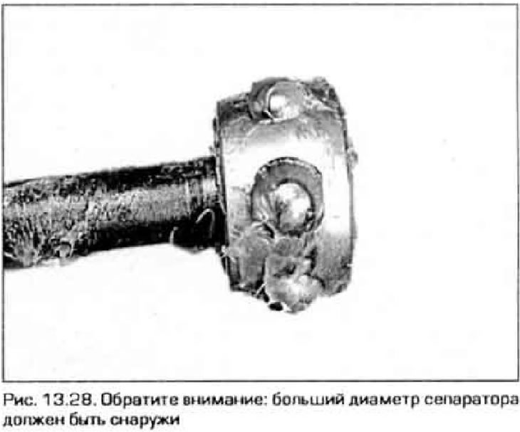
28. Slide the pivot assembly onto the drive shaft so that the smaller cage diameter is inside (pic. 13.28).
29. Insert the circlip into the groove of the shaft. Lift the inner link of the hinge outward to make sure it is secure.
30. Fill grease into the pivot housing until it completely fills the entire housing.
31. Install the bearing circlip.
32. Remove excess grease from the boot groove on the pivot housing. Slide the cover onto the drive shaft so that it fits into the groove of the drive shaft. Put the cover on the hinge body.
33. Insert a small screwdriver between the boot and hinge body and equalize the air pressure inside the boot (see fig. 13.13). Do not damage the case.
34. Adjust the length of the input shaft according to technical data (see fig. 13.14).
35. Tighten the clamps fastening the case (see Figure 13.15,a-d). Move on to the next item.
For all internal hinges
35. Install a new retaining ring on the inner joint shaft (see fig. 11.10, a, b).
36. Install the drive shaft on the car (see paragraph 11).
External hinge
37. Remove the boot clamps (see fig. 13.Z, a, b) and pull the cover back so that you can inspect the hinge.
38. Thoroughly wash the joint in solvent and dry it with compressed air (if there is such a possibility). The outer hinge is non-separable, which makes it difficult to clean it from old grease. However, if you have patience, cleaning the hinge is quite possible.
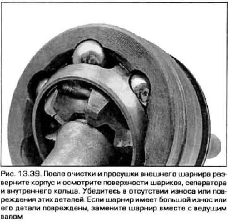
39. Expand the pivot housing to reveal the balls, inner race, and cage. Inspect these components for wear or damage. If necessary, replace the joint together with the drive shaft (pic. 13.39).
40. If the cover of the outer hinge is damaged, and the hinge itself is in good condition, remove the inner hinge and the outer hinge cover (removal of the three-finger type internal hinge is described in paragraphs. 3-9, and the removal of the ball-type hinge - in paragraphs. 18-24). If a dynamic damper is installed on the shaft, mark its position relative to the shaft, then remove the yoke and damper.
41. Put on a new cover of the external hinge on a leading shaft. To prevent damage to the boot, wrap the end of the drive shaft with electrical tape (see figure 13.10). After that, put fresh grease into the outer joint and its boot Put the boot on the joint, equalize the air pressure in it and secure it with new clamps (see fig. 13.15, a-d). Install a dynamic damper on the drive shaft (if it exists) and secure it with a new clamp, aligning the marks on the shaft and damper (see par. 40). Tighten the damper mounting xowyi.
42. Put on the drive shaft a collar of smaller diameter, a cover of the inner hinge and install the inner hinge (installation of a three-finger type internal hinge is described in paragraphs. 10-15, and the installation of a ball-type hinge - in p.p. 25-35). Adjust the length of the drive shaft before tightening the inner joint boot clamps.
43. Install the drive shaft on the car (see paragraph 11).