
MazBook.ru
English Русский
Български
Беларускі
Український
Српски
Hrvatski
Română
Polski
Slovenský
Magyar
• Bookmark • Sitemap • Contacts •   
Cars Opel Cars Ford Cars Volkswagen Cars Audi Cars Kia Cars Renault Cars Peugeot


Familia Capella Mazda3 Mazda6 CX-? Others Articles
Capella 3 (1982-1992, petrol) Capella 3 and 4 (1982-1992) Capella 4 (1987-1992) Capella 5 (1991-1997) Capella 6 (1997-2005, petrol)

Clutch Components — removal, inspection, and installation (Mazda Capella GF)

  • Home
  • Mazda Capella
  • Capella GF (1997-2005)
  • Transmission
  • Clutch and drive shafts
  • Clutch Components — removal, inspection, and installation
0
Contents: Removal ⇓ Examination ⇓ Installation ⇓
Caution! When the clutch disc wears, dust containing asbestos is formed, which is hazardous to your health. DO NOT remove dust with compressed air or inhale it, DO NOT use gasoline or gasoline-based solvents to clean clutch components. Brake system cleaner can be used to clean the components. Wipe the clutch components with a clean cloth. then throw it away in a closed container.


Removal


1. To access the clutch components, it is necessary to remove the gearbox without removing the engine from the vehicle. If, of course, the engine is removed from the car (in case of serious breakdown), it makes sense to disassemble the clutch and inspect its condition at the same time. The relatively low cost and high labor intensity of accessing clutch components make it advisable to replace them every time the engine or gearbox is disassembled, without waiting for the clutch components to wear out or break. If the engine cannot be removed, the following procedures must be performed.

2. Remove the gearbox from the vehicle (see chapter 7A). When removing the gearbox, place supports under the engine. It is preferable to support the engine from above. However, if you are going to place a jack under the engine, place a wooden block between the jack and the engine (to distribute the load).

Caution: The oil pump pickup pipe is located close to the bottom of the engine sump. If the pan bends, you can damage the intake pipe, which will result in insufficient lubrication of the engine.


3. The release fork and bearing must remain on the gearbox housing.

4. To support the clutch disc while removing the pressure plate assembly, insert a disc centering tool.

5. Carefully inspect the flywheel and pressure plate housing and locate the timing marks on them. Typically the marks are in the form of X or 0 signs or in the form of a letter painted in white paint. If you do not find marks, apply them to the housing and to the flywheel to facilitate correct assembly of the clutch (figure 6.5).
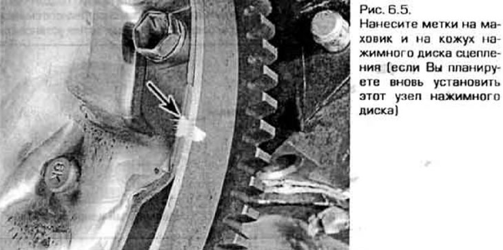
5. Carefully inspect the flywheel and pressure plate housing and locate the timing marks on them.…


6. Gradually loosen the bolts securing the pressure plate housing to the flywheel (figure 6.6). Loosen the bolts in a diagonal order evenly until the spring is completely released. Then, supporting the pressure plate, remove the bolts, remove the pressure plate assembly, diaphragm spring and clutch disc.
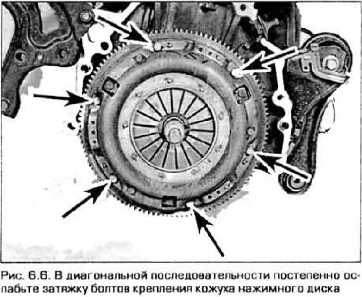
6. Gradually loosen the bolts securing the pressure plate housing to the flywheel (figure 6.6).…


Examination


7. A common clutch fault is excessive wear of the clutch disc linings. However, when disassembling the clutch, it is necessary to carefully inspect all components.

8. Inspect the flywheel surface and ensure there are no cracks, signs of overheating or scuffs. If the defects are small, they can be eliminated by grinding the flywheel (we recommend performing this operation regardless of the condition of the flywheel surface). Flywheel crushing and installation are described in Chapter 2.

9. Inspect the clutch disc linings. The distance from the working surface of the pads to the rivets that attach them to the base should be at least 1.6 mm. Check for cracks in the pads and the condition of the rivets, as well as the serviceability of the springs (figure 6.9). Usually, when disassembling the clutch, the clutch disc is replaced in any case. Also, if you are not sure that the disk is completely functional, replace it as well.
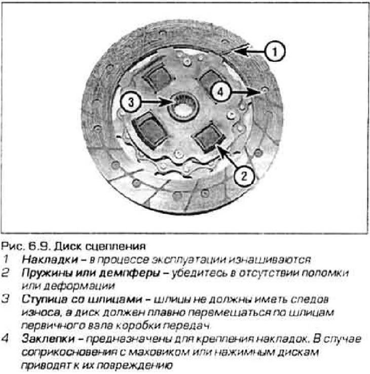
9. Inspect the clutch disc linings. The distance from the working surface of the pads to the rivets…


10. The release bearing is also replaced together with the clutch disc (see paragraph 7).

11. Inspect the surface of the pressure plate and the diaphragm spring (fig. 6.11, a, b). If the disc surface has a ring groove or other damage, replace the pressure plate assembly. Check for obvious damage (cracks, chips, etc.). Minor defects on the surface of the disc can be corrected using sandpaper. If there is serious damage, purchase a new or refurbished unit.
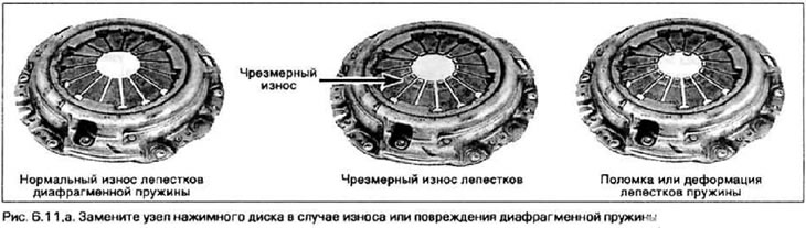
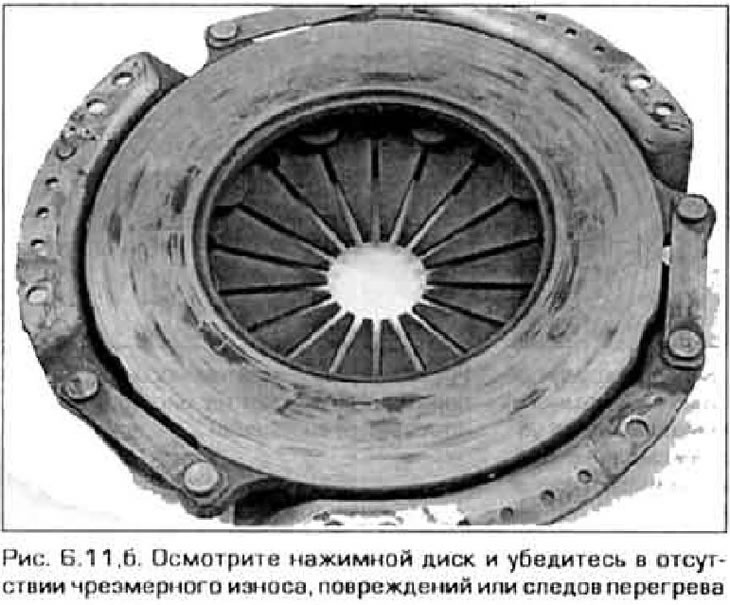

11. Inspect the surface of the pressure plate and the diaphragm spring (fig. 6.11, a, b). If the…


11. Inspect the surface of the pressure plate and the diaphragm spring (fig. 6.11, a, b). If the…


12. Inspect the bearing installed at the end of the crankshaft and make sure it is not worn or otherwise damaged. Replace the bearing if necessary.

13. To remove the bearing you will need a special tool or a suitable puller (figure 6.13). This is a device (or puller) can be purchased at the related goods store.
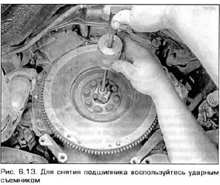
13. To remove the bearing you will need a special tool or a suitable puller (figure 6.13). This is…


Installation


14. Before installing the new crankshaft bearing, apply a small amount of grease to its outer ring, then install the bearing in place (using a hammer or device) (figure 6.14).
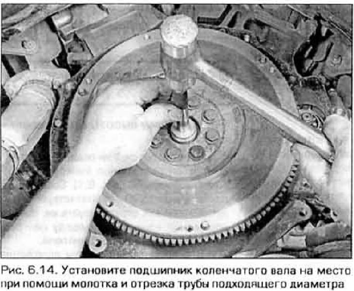
14. Before installing the new crankshaft bearing, apply a small amount of grease to its outer ring,…


15. Before assembling the clutch, thoroughly wipe the surface of the flywheel and pressure plate with brake cleaner or acetone. It is very important that there are no traces of oil on these surfaces. Install these parts only with clean hands.

16. Using a special tool, center the clutch disc in place with the pressure plate (figure 6.16). Make sure all components are installed correctly. Most clutch discs are marked "to flywheel" or something similar. If there is no mark on the disc, install it so that the linings on the damper springs are facing the gearbox.
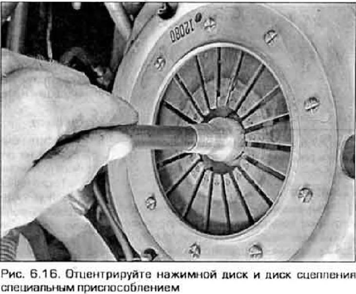
16. Using a special tool, center the clutch disc in place with the pressure plate (figure 6.16).…


17. Wrap it up (only by hand) bolts securing the pressure plate housing to the flywheel. Tighten the bolts evenly.


18. Center the cordon disk. Make sure the tool fits into the clutch disc splines and the bearing on the crankshaft. Move the tool from side to side to center the clutch disc. Screw in the pressure plate housing mounting bolts evenly and diagonally until they are fully tightened. Do not allow the pressure plate to become tilted. After you have tightened all the bolts, tighten them to the specified torque. Remove the centering tool.

19. Lubricate the release bearing with high-temperature grease (see paragraph 7). Also apply a little grease to the working surfaces of the clutch fork, as well as to the neck of the gearbox input shaft cover (along which the release bearing moves).

20. Install the release bearing (see paragraph 7).

21. Install the gearbox and all previously removed components.
This article is available at: russian, bulgarian, belarusian, ukrainian, serbian, croatian, romanian, polish, slovak, hungarian
This text was checked by: German Vorobyov
Share with friends on social networks:

Previous
Capella 6 » Clutch and drive shafts
Next

Clutch hydraulic system — bleeding
Clutch slave cylinder — removal, repair and installation
Clutch Master Cylinder — removal and installation
Clutch — description and testing
Basic information about clutches and drive shafts
Clutch release bearing and fork — removal, inspection and installation
Clutch pedal adjustment
Clutch Pedal Start Switch — checking, replacing, and adjusting
Drive shafts — basic information and inspection
Drive shafts — removal and installation
More articles on repairing other Mazda models
Detailed technical specifications of the clutch Mazda Familia 5 (1985-1989)
Fuel and exhaust system components Mazda3 BK (2003-2009)
Cooling system components Mazda6 GG (2002-2008)
Checking the clutch mechanism components Mazda CX-5KE (2012-2017)
Clutch — design description Mazda 121 (3) (1996-2003)
Link in different formats to this article
Comments and feedback from visitors
No comments yet


How much will 48 + 49 ?


Capella 6 (1997-2005, petrol) 
  • General information
  • Introduction to guide
  • User manual
  • Troubleshooting
  • Maintenance
  • Power unit
  • 4-cylinder engines
  • 6-cylinder engines
  • Engine overhaul
  • Cooling and ventilation
  • Power and exhaust systems
  • Engine electrics
  • Control system
  • Transmission
  • Mechanical gearbox
  • Automatic gearbox
  • Clutch and drive shafts
  • Chassis
  • Brake system
  • Car suspension
  • Steering
  • Body
  • Exterior (external elements)
  • Interior (internal elements)
  • Doors, windows and locks
  • Electrical equipment
  • Equipment and devices
  • Electrical circuits
Capella 5 (1991-1997) 
  • General information
  • User manual
  • Maintenance
  • Helpful hints
  • Power unit
  • Petrol engines 1.6 and 1.8
  • Petrol engines 2.0
  • 2.5 petrol engines
  • Overhaul engines 1.6 and 1.8
  • Overhaul engines 2.0 and 2.5
  • Diesel engine 2.0
  • Engine electrics
  • Cooling system
  • Air conditioner
  • Carburetor Nikki 30/34
  • Power system (1.6 and 1.8)
  • Power system (2.0 and 2.5)
  • Control system
  • Transmission
  • Mechanical gearbox
  • Automatic gearbox
  • Clutch and axles
  • Chassis
  • Brake system
  • Suspension and wheels
  • Steering
  • Body
  • Exterior (external elements)
  • Interior (internal elements)
  • Doors and windows
  • Electrical equipment
  • Equipment and devices
  • Electrical circuits
Capella 4 (1987-1992) 
  • General information
  • Introduction to manual
  • Vehicle specifications
  • Power unit
  • Engine repair
  • Lubrication system
  • Cooling system
  • Fuel system (carburetor)
  • Fuel injection (FE)
  • Fuel injection (DOHC)
  • Fuel system (diesel)
  • Ignition system
  • Transmission
  • Clutch
  • Gearbox
  • Drive shafts
  • Chassis
  • Front suspension
  • Rear suspension
  • Steering system
  • Brake system
  • Electrical equipment
  • Equipment and devices
  • Electrical circuits
Capella 3 and 4 (1982-1992) 
  • General information
  • User manual
  • Maintenance
  • Power unit
  • Gasoline engine
  • Engine overhaul (gasoline)
  • Diesel engine
  • Cooling and heating
  • Supply system
  • Ignition system
  • Emission reduction
  • Transmission
  • Clutch
  • Mechanical gearbox
  • Automatic gearbox
  • Drive shafts
  • Chassis
  • Brake system
  • Suspension and wheels
  • Steering
  • Body
  • Exterior (external elements)
  • Interior (internal elements)
  • Electrical equipment
  • Equipment and devices
  • Power devices
  • Electrical circuits
Capella 3 (1982-1992, petrol) 
  • General information
  • User manual
  • Maintenance
  • Troubleshooting
  • Late models
  • Power unit
  • Engine in car
  • Engine overhaul
  • Cooling and heating system
  • Fuel and exhaust system
  • Engine electrical system
  • Emission control system
  • Transmission
  • Mechanical gearbox
  • Automatic gearbox
  • Clutch and drive shafts
  • Chassis
  • Brake system
  • Suspension and wheels
  • Steering
  • Body
  • Exterior (external elements)
  • Interior (internal elements)
  • Electrical equipment
  • Equipment and devices
  • Lighting and lamps
  • Electrical circuits
MazBook.ru © 2018–2026 · Mobile version · Articles and news · Sitemap: EN BG BY UA RS HR RO PL SK HU · Feedback · Site search · Add to bookmarks Familia 5 (BF) · Familia 6 (BG) · Capella 3 (GC) · Capella 3 and 4 (GC) · Capella 4 (GD) · Capella 5 (GE) · Capella 6 (GF) · Mazda3 BK · Mazda6 GG · CX-5KE · Mazda 121 (3) · Mazda BT-50 (1) ·
By continuing to use the site, you agree to the use of cookies 🔐