
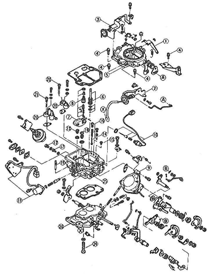
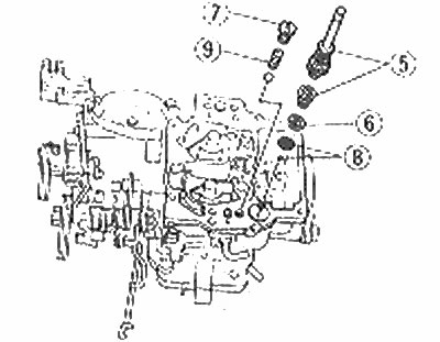
Carburetor Components - UK Models
1. Lever (accelerator pump); 2. Vacuum cut-off diaphragm and bracket; 3. Damper opening diaphragm and bracket; 4. Screws; 5. Air mouth; 6. Accelerator pump; 7. float; 8. Needle of a float regulator; 9. Secondary chamber throttle diaphragm; 10. Solenoid valve for breaking cold mode. move; 11. Eco solenoid valve when coasting and cold switch. move; 12. Cork; 13. The main jet of the primary chamber; 14. Slow moving jet primary chamber; 15. Air jet of a slow walk of the primary chamber (№2); 16. Injection weight; 17. The main jet of the secondary chamber; 18. Power jet; 19. Slow jet secondary chamber; 20. Main air jet of the primary chamber; 21. The main air jet of the secondary chamber; 22. Primary chamber diffuser and atomizer; 23. Secondary chamber diffuser and atomizer; 24. Bolt; 25. Carburetor body; 26. Throttle body
Note: Carburetor repair is a procedure that requires experience. A car owner without much experience should have this procedure carried out by the maintenance department.
Check the availability and readiness of spare parts before starting work. It is more efficient to replace components with new ones than to repair a worn block.
Dismantling
1. Clean the outside of the carburetor with solvent and dry it. Place the carburetor on a clean workbench. Prepare many small containers.
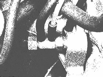
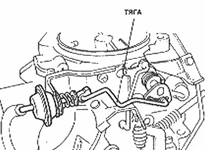
2. Examine the throttle valve and thrust of the accelerator pump. Make notes if they differ from those shown in the photo.
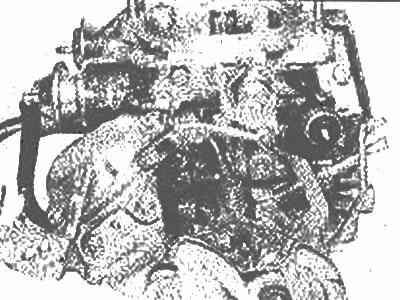
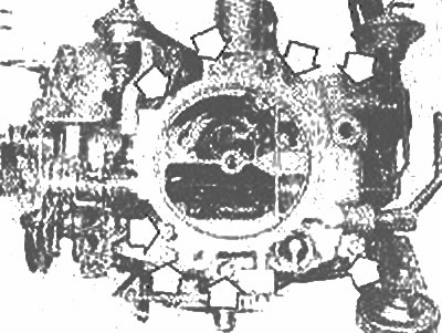
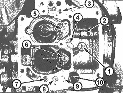
View of the carburetor from the throttle link side | 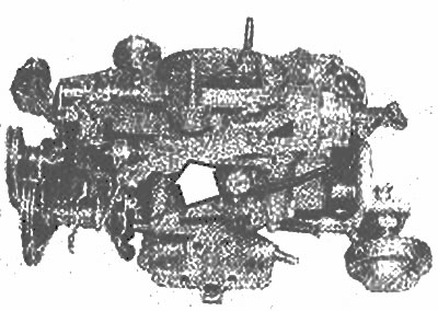
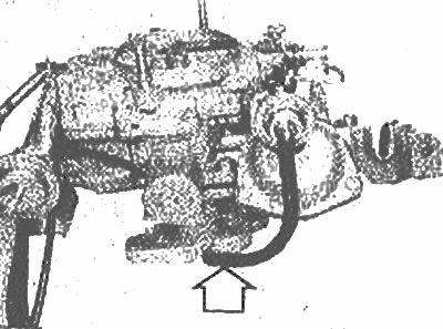
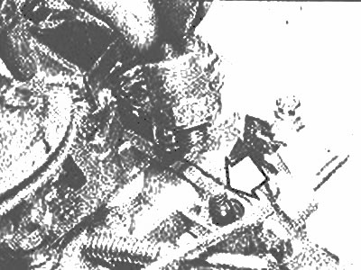
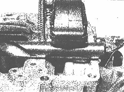
View of the carburetor from the side of the shock absorber. Accelerator pump lever marked with arrows |
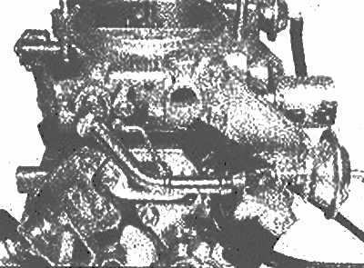
View of the carburetor from the fuel inlet side
3. Disconnect the accelerator pump lever from the throttle linkage. Disconnect the lever spring.
The main components of the carburetor accelerator pump
5. Assembling the accelerator pump plunger; 6. Mounting bracket; 7. Control valve plug; 8. Strainer and accelerator pump inlet control ball; 9. Ball exit booster
4. Disconnect the vacuum hose from the rod on the throttle body (photo).
Disconnect the cut-off vacuum hose (marked with an arrow)
5. Disconnect the linkage from the quick cool damper shaft lever. move.
6. Remove the eight screws that secure the air inlet to the carburetor body (photo). The screws are not the same length: note their location.
eight screws (soaked with arrows) sprinkling the air cap to the carburetor body
7. Raise the air inlet, clearing the wiring harness and all other obstructions. Take the pad. The piston of the accelerator pump can be removed with an air cap.
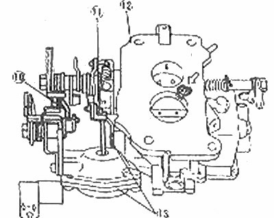
The thrust of the main part of the carburetor throttle (10), vacuum diaphragm thrust (11), throttle body (12) and diaphragm assembly (13)
The arrow shows the screw securing the throttle body
8. Now you can clean the float reservoir and various jets and pump (photo).
Carburetor body with air inlet removed
1. The main jet of the primary chamber; 2. The main jet of the secondary chamber (in the pipe); 3. Slow speed jet of the secondary chamber; 4. Power jet; 5. The main air jet of the secondary chamber; 6. Main air jet of the primary chamber; 7. Air jet slow stroke primary chamber (№ 2); 8. Slow jet primary chamber; 9. Injection weight; 10. Accelerator pump spring
9. The float and float regulator needle can be removed from the air inlet by removing the float pivot pin (photo). Then you can unscrew the seat of the needle of the float regulator.
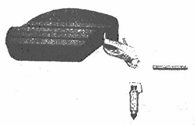
Float, float needle and pivot pin
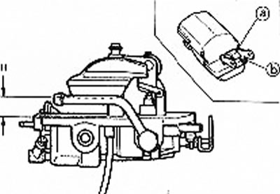
10. To remove the cold interrupt solenoid valve. stroke, unscrew it from the carburetor body. Remove spring and plunger (photo).
Removing the solenoid valve for breaking through the cold mode. move. Spring and plunger (marked with an arrow) stayed in the building
11. Remove shock absorber, ECO valve when coasting, and cold switch. move (where equipped). See Section 6 if necessary.
12. If necessary, the secondary throttle diaphragm and vacuum flap blocks can be removed along with their brackets. The throttle diaphragm assembly can be removed for inspection, but a repair kit is unlikely to be found.
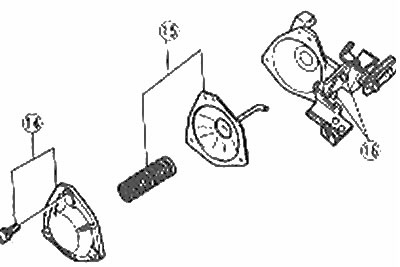
Vacuum Diaphragm Components
14. Cover and screws; 15. Spring and diaphragm; 16. Throttle lever
13. If you want to separate the throttle body from the carburetor body, note that one of the mounting screws is below, behind the throttle body of the secondary chamber.
14. Remove the idle adjustment screw, counting the number of turns.
Cleaning and inspection
15. Wash all components in clean solvent and blow dry with compressed air. Do not use a piece of the passage to clean the jets and channels.
16. Electromagnetic block for interrupting the cold mode. strokes, diaphragms and other electrical, rubber and plastic parts must not be immersed in various solvents.
17. Make sure all fuel passages, jets, and other components are free of burrs and dirt.
18. Inspect the upper and lower surfaces of the air cap, main parts of the throttle body for signs of damage. Make sure all foreign particles are removed.
19. Inspect all lever bores and plastic bushings for signs of excessive wear and replace if necessary.
20. Inspect the float regulator needle and seat for signs of dirt, if there are deep nicks, replace the entire block.
21. Inspect the float, float arms and pivot pin for signs of distortion (deformations) or brake and align or replace as needed.
22. Inspect the rubber seal on the accelerator pump plunger for excessive wear and cracks.
23. Inspect the mixture adjusting screw for signs of burrs or ridges.
24. Check choke and linkages for excessive wear, restrictions and distortion and deformation and align or replace as needed.
25. Inspect the throttle vacuum diaphragm for signs of leaks and replace if necessary.
26. Check the freedom of movement of the air damper.
27. Check the retracting action by connecting the solenoid block traction relay to the positive pole of the battery and the housing. The valve stem must then retract the valve body. If this does not happen, replace the traction relay with a new one.
28. Vacuum damper opening diaphragm is controlled by a thermal valve, which is screwed into the intake manifold (photo). The valve must not pass air below 19°C, but must freely pass air above this temperature. Operating temperature tolerance±3°C. Remove the valve for inspection as shown.
Thermo valve for opening the damper on the intake manifold
Assembly
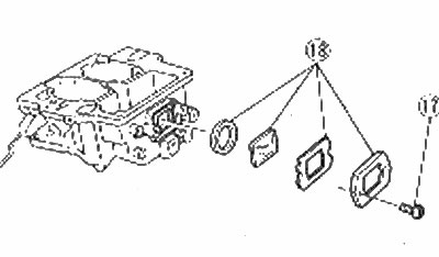
Assembling the glass lumen of the fuel reservoir in the main part of the carburetor
17. Screws; 18. Cover, gasket, glass and rubber gasket
29. Carburetor assembly is basically the reverse of dismantling, paying attention to the following points:
- a) Use all new gaskets.
- b) Set the mixture adjusting screw to the same number of revolutions recorded during removal.
- c) Perform the adjustment described in the following paragraphs.
Adjustment
Height of the upper position of the float of the air cap
30. Before installing the air cap, the top position of the float must be measured (without gasket) and adjust as follows.
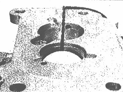
- A) Turn the air inlet over, allow the float to drop under its own weight and measure the gap between the float and the air inlet (photo). Compare measurement (H in the corresponding illustration) to Specifications, and adjust the float tip seal as needed.
- b) Rotate the air inlet strut, allow the float to lower and measure the distance between the base of the float and the air inlet. If the gap (L in the corresponding illustration) incorrect, bend the float stop.
Using a Sperlo to Measure the Height of a Float
Float position parameters and adjustment procedure (with housing removed) | 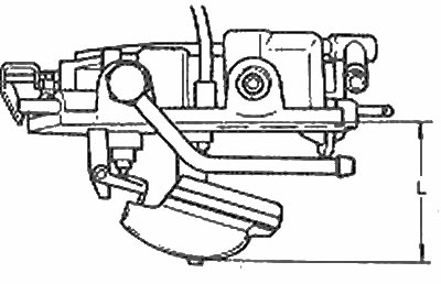
Float position parameters and adjustment procedure |
Damper opening diaphragm
31. Create a vacuum of approximately 15.7 inHg. on the tube of the vacuum diaphragm opening the damper. Push the choke slightly to close it and measure the gap.
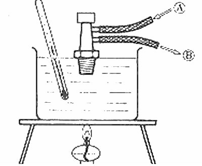
Checking the thermal valve for opening the damper
A - Incoming air; B - Exhaust air
Checking the clearance of the damper opening diaphragm Standard gap = 3.94±0.16mm | 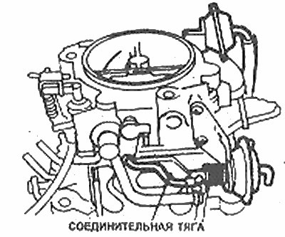
Adjust the damper opening diaphragm clearance by bending the connecting rod |
Vacuum cut-off diaphragm
32. Checking is similar to the procedure described for the damper opening diaphragm, but this time the desired air damper gap is 1.94±0.25 mm. Bend the tie rod if necessary.
Connecting rod vacuum diaphragm cut-off
Fast cooling adjustment move
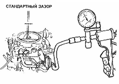
33. Close the choke completely and measure the gap between the throttle valve of the primary chamber and the chamber using a drill or a measuring stick (photo). The desired clearance is given in the Specifications. Adjust if necessary by bending the quick-release tie rod. move.
Fast cooling adjustment stroke - measurement of the throttle valve clearance of the primary chamber | 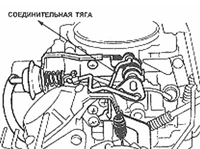
Connecting draft of fast cold. move |
Throttle lock
34. Check that the secondary throttle does not open freely until the primary throttle has opened 45°C. At this angle, the gap between the throttle valve of the primary chamber and the chamber is 6.7±0.5 mm. Also check that the secondary throttle is free to fully open when the primary throttle is fully open. Adjust if necessary by bending the lock lever.
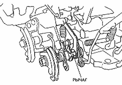
Throttle lock lever
Note: The secondary chamber throttle must be opened manually as it is normally opened by vacuum and not mechanically.
Idle speed and mixture
35. Install the carburetor (Chapter 7), warm up the engine and adjust the idle speed and mixture (Section 1). Finally install where new plugs are required.