MazBook.ru
English Русский
Български
Беларускі
Український
Српски
Hrvatski
Română
Polski
Slovenský
Magyar
• Bookmark • Sitemap • Contacts •   
Cars Opel Cars Ford Cars Volkswagen Cars Audi Cars Kia Cars Renault Cars Peugeot


Familia Capella Mazda3 Mazda6 CX-? Others Articles
Capella 3 (1982-1992, petrol) Capella 3 and 4 (1982-1992) Capella 4 (1987-1992) Capella 5 (1991-1997) Capella 6 (1997-2005, petrol)

Heating and ventilation (Mazda Capella GC)

  • Home
  • Mazda Capella
  • Capella GC (1982-1992)
  • General information
  • User manual
  • Heating and ventilation
0
Contents: Central ventilation nozzles ⇓ Side ventilation nozzles ⇓ Heating and ventilation control panel ⇓ Heating ⇓ Air conditioner ⇓

Central ventilation nozzles
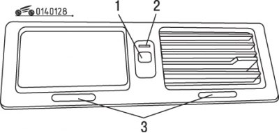


Figure 1.28. Central ventilation nozzles: 1 – rotary switch; 2 – indicator; 3 – manual adjustment…

Figure 1.28. Central ventilation nozzles: 1 – rotary switch; 2 – indicator; 3 – manual adjustment handles


The central rotating ventilation nozzles can rotate automatically (figure 1.28). Pressing the switch again turns them off again. When the rotating nozzles are turned off, the air flow direction can be manually adjusted.

Side ventilation nozzles


Air flows can be adjusted independently of each other.

The amount of air supplied through the side ventilation nozzle depends on the fan speed.

Ventilation is off.

The amount of incoming air depends on the vehicle speed.

Attention!
With the air conditioner on, set the lever to or on
For heating, set the lever to the position
If the lever is set to position the side windows will be defrosted.


Heating and ventilation control panel


Figure 1.29. Heating and ventilation control panel: 1 – air flow distribution adjustment lever;…

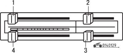
Figure 1.29. Heating and ventilation control panel: 1 – air flow distribution adjustment lever; 2-switch lever "fresh/recirculated air"; 3 – fan speed switch; 4 – air temperature control lever


The heating and ventilation control panel is shown in the figure 1.29.

Air flow adjustment


The air flow distribution control lever allows you to set the air outlet from the different ventilation nozzles.

Switching "fresh/recirculated air"


The fresh/recirculated air selector lever can be used to control whether fresh air or recirculated air is supplied to the vehicle interior.

Temperature control
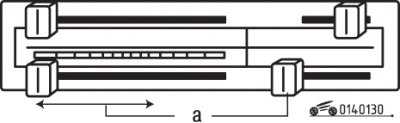


Figure 1.30. Position (a) of the heating and ventilation control levers when adjusting the…

Figure 1.30. Position (a) of the heating and ventilation control levers when adjusting the temperature of the air supplied to the vehicle interior


The temperature control lever allows you to adjust the temperature of the air supplied to the vehicle's interior (figure 1.30).

Fan speed switch


The switch can be set to the following positions:
  • OFF - the fan is off;
  • 1 - low speed;
  • 2 - average rotation frequency;
  • 3 - high speed;
  • 4 - very high rotation speed.

(Original material on the website: «www.MAZbook.ru»)

Turning off the fresh air supply


Turn off the fan. Set the fresh/recirculated air selector lever to the appropriate position. Close the side vents.

Air supply to the upper cabin space and foot area
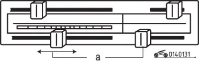


Figure 1.31. Position (a) of the heating and ventilation control levers when supplying air to the…

Figure 1.31. Position (a) of the heating and ventilation control levers when supplying air to the upper cabin space and to the footwell area


This is done after setting the air flow distribution adjustment lever to the appropriate position (figure 1.31).

Heating
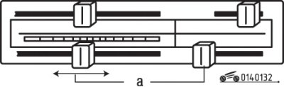


Figure 1.32. Position (a) of the heating and ventilation control levers when heating the vehicle…

Figure 1.32. Position (a) of the heating and ventilation control levers when heating the vehicle interior


To heat the vehicle interior, set the levers on the heating and ventilation control panel to the positions shown in the figure 1.32.

Heating and defrosting
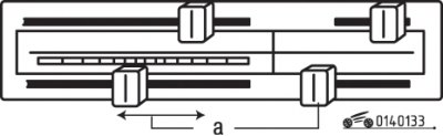


Figure 1.33. Position (a) of the heating and ventilation control levers during heating and de-icing

Figure 1.33. Position (a) of the heating and ventilation control levers during heating and de-icing


To heat and de-ice, set the levers on the heating and ventilation control panel to the positions shown in the illustration 1.33.

Windshield de-icing


Before starting to move, clear the windshield, side windows, rear window, and rearview mirror of ice and snow.

Remove ice and snow from the air intake grille to improve heating and heater efficiency and prevent windshield fogging.
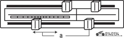
Figure 1.34. Position (a) of the heating and ventilation control levers during heating and de-icing

Figure 1.34. Position (a) of the heating and ventilation control levers during heating and de-icing


To heat and defrost the windshield, set the levers on the heating and ventilation control panel to the positions shown in the illustration 1.34.

Air conditioner


Air conditioner operating mode


1. Close the side fresh air vents.

2. Set the temperature control lever to the required position.

3. Start the engine, press the air conditioner switch and set the desired fan speed.

4. Set the maximum performance as follows.

Move the temperature setting lever all the way to the left, the fresh/recirculated air selector lever to the recirculated air position, and set the fan speed to mode "4" (see Figure 1.29).

Air conditioner switch


The air conditioner can be turned on or off by pressing the air conditioner switch.

Important! Even if the air conditioner is not used for an extended period of time, it should still be turned on once a week for a few minutes to lubricate the internal parts of the air conditioner compressor.
This article is available at: russian, bulgarian, belarusian, ukrainian, serbian, croatian, romanian, polish, slovak, hungarian
This text was checked by: Georgy Afanasyev
Share with friends on social networks:

Previous
Capella 3 and 4 » User manual
Next

Controls, instrumentation and equipment
Glass cleaners and washers
Lighting and light signaling
Device for maintaining a constant speed of movement (cruise control)
Technical characteristics of gearboxes
Interior lighting
Electric tilt-and-slide sunroof
Parking brake
Starting the engine from an external power source
Starting the engine by towing
More articles on repairing other Mazda models
A. Schemes of battery charging, starting system, heating element of… Mazda Familia 5 (1985-1989)
Adjusting the ventilation deflectors Mazda3 BK (2003-2009)
Adjusting the ventilation deflectors Mazda6 GG (2002-2008)
Electric heating — general information Mazda CX-5KE (2012-2017)
Heating and ventilation system (2000-2001) Mazda 121 (3) (1996-2003)
Link in different formats to this article
Comments and feedback from visitors
No comments yet


How much will 22 + 47 ?


Capella 6 (1997-2005, petrol) 
  • General information
  • Introduction to guide
  • User manual
  • Troubleshooting
  • Maintenance
  • Power unit
  • 4-cylinder engines
  • 6-cylinder engines
  • Engine overhaul
  • Cooling and ventilation
  • Power and exhaust systems
  • Engine electrics
  • Control system
  • Transmission
  • Mechanical gearbox
  • Automatic gearbox
  • Clutch and drive shafts
  • Chassis
  • Brake system
  • Car suspension
  • Steering
  • Body
  • Exterior (external elements)
  • Interior (internal elements)
  • Doors, windows and locks
  • Electrical equipment
  • Equipment and devices
  • Electrical circuits
Capella 5 (1991-1997) 
  • General information
  • User manual
  • Maintenance
  • Helpful hints
  • Power unit
  • Petrol engines 1.6 and 1.8
  • Petrol engines 2.0
  • 2.5 petrol engines
  • Overhaul engines 1.6 and 1.8
  • Overhaul engines 2.0 and 2.5
  • Diesel engine 2.0
  • Engine electrics
  • Cooling system
  • Air conditioner
  • Carburetor Nikki 30/34
  • Power system (1.6 and 1.8)
  • Power system (2.0 and 2.5)
  • Control system
  • Transmission
  • Mechanical gearbox
  • Automatic gearbox
  • Clutch and axles
  • Chassis
  • Brake system
  • Suspension and wheels
  • Steering
  • Body
  • Exterior (external elements)
  • Interior (internal elements)
  • Doors and windows
  • Electrical equipment
  • Equipment and devices
  • Electrical circuits
Capella 4 (1987-1992) 
  • General information
  • Introduction to manual
  • Vehicle specifications
  • Power unit
  • Engine repair
  • Lubrication system
  • Cooling system
  • Fuel system (carburetor)
  • Fuel injection (FE)
  • Fuel injection (DOHC)
  • Fuel system (diesel)
  • Ignition system
  • Transmission
  • Clutch
  • Gearbox
  • Drive shafts
  • Chassis
  • Front suspension
  • Rear suspension
  • Steering system
  • Brake system
  • Electrical equipment
  • Equipment and devices
  • Electrical circuits
Capella 3 and 4 (1982-1992) 
  • General information
  • User manual
  • Maintenance
  • Power unit
  • Gasoline engine
  • Engine overhaul (gasoline)
  • Diesel engine
  • Cooling and heating
  • Supply system
  • Ignition system
  • Emission reduction
  • Transmission
  • Clutch
  • Mechanical gearbox
  • Automatic gearbox
  • Drive shafts
  • Chassis
  • Brake system
  • Suspension and wheels
  • Steering
  • Body
  • Exterior (external elements)
  • Interior (internal elements)
  • Electrical equipment
  • Equipment and devices
  • Power devices
  • Electrical circuits
Capella 3 (1982-1992, petrol) 
  • General information
  • User manual
  • Maintenance
  • Troubleshooting
  • Late models
  • Power unit
  • Engine in car
  • Engine overhaul
  • Cooling and heating system
  • Fuel and exhaust system
  • Engine electrical system
  • Emission control system
  • Transmission
  • Mechanical gearbox
  • Automatic gearbox
  • Clutch and drive shafts
  • Chassis
  • Brake system
  • Suspension and wheels
  • Steering
  • Body
  • Exterior (external elements)
  • Interior (internal elements)
  • Electrical equipment
  • Equipment and devices
  • Lighting and lamps
  • Electrical circuits
MazBook.ru © 2018–2026 · Mobile version · Articles and news · Sitemap: EN BG BY UA RS HR RO PL SK HU · Feedback · Site search · Add to bookmarks Familia 5 (BF) · Familia 6 (BG) · Capella 3 (GC) · Capella 3 and 4 (GC) · Capella 4 (GD) · Capella 5 (GE) · Capella 6 (GF) · Mazda3 BK · Mazda6 GG · CX-5KE · Mazda 121 (3) · Mazda BT-50 (1) ·
By continuing to use the site, you agree to the use of cookies 🔐