
The combination of these or those systems is determined by the year of manufacture of the car, the place of its initial delivery to the consumer and the type of gearbox. This manual covers the following main systems installed on vehicles:
- electronic ignition system;
- air injection system;
- air-fuel mixture lean system when the vehicle is in neutral gear;
- system to reduce toxicity with a sharp closing of the throttle;
- automatic air temperature control system at the carburetor inlet;
- forced crankcase ventilation system.
This section also describes the ECO driving indicator system, which is part of the neutral lean system control unit, although it is not directly related to the emission control system. For each of the above systems, a device is described, a performance check (subject to the possibility of), replacement of components and assemblies (for systems where it is allowed).
Before drawing a conclusion about a malfunction of the exhaust gas toxicity reduction system, carefully check the ignition and power systems. In some cases, only specially trained personnel using special tools and equipment can accurately determine the causes of unsatisfactory operation or difficult starting of the engine. If inspection and maintenance becomes difficult or work cannot be carried out within the framework of a local workshop, consult your local dealer for advice. However, this does not mean that emission control systems are very difficult to maintain and repair. You can easily carry out many checks yourself and with the help of common tools and devices, you can carry out most of the routine maintenance work (and possibly fulfill them completely).
Attention! The most common cause of malfunctions in emission control systems is often as little as a loose vacuum hose seal or damage to the vacuum hose or electrical connections. Therefore, always check the hoses and wires first.
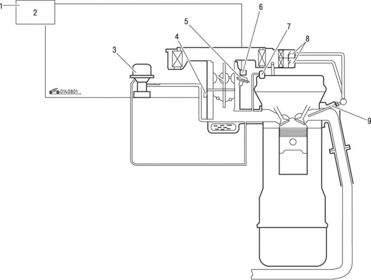
Pic. 8.1. The main elements of the exhaust gas toxicity reduction system: 1 - to the ignition system; 2 - control unit; 3 - flame arrester; 4 – forced idle economizer switch; 5 - pneumatic shock absorber for closing the throttle; 6 - leaner air-fuel mixture when driving in neutral gear; 7 - spool device of the forced crankcase ventilation system; 8 - reed valves; 9 - air jet
Please read the warnings in this section very carefully. It should be noted that the diagram in Fig. 8.1 may not fully match the system that is installed on your car, due to changes made annually by the manufacturer.