
MazBook.ru
English Русский
Български
Беларускі
Український
Српски
Hrvatski
Română
Polski
Slovenský
Magyar
• Bookmark • Sitemap • Contacts •   
Cars Opel Cars Ford Cars Volkswagen Cars Audi Cars Kia Cars Renault Cars Peugeot


Familia Capella Mazda3 Mazda6 CX-? Others Articles
Capella 3 (1982-1992, petrol) Capella 3 and 4 (1982-1992) Capella 4 (1987-1992) Capella 5 (1991-1997) Capella 6 (1997-2005, petrol)

Fuel economy indicator system (Mazda Capella GC)

  • Home
  • Mazda Capella
  • Capella GC (1982-1992)
  • Power unit
  • Emission reduction
  • Fuel economy indicator system
0
Contents: Technical condition check ⇓ Replacement of components ⇓
Some models with a manual transmission are equipped with an economy driving mode indicator system. The instrument cluster has two warning lights, which the driver uses to either shift into a higher gear or slightly close the throttle, which reduces fuel consumption.

The light indicator does not work in 5th (highest) gear and during sudden engine braking. On models produced in 1984 and later, the indicator light works in all gears except reverse.
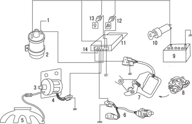
Figure 8.7. Components included in the fuel-efficient driving mode indicator system: 1 – to the…

Figure 8.7. Components included in the fuel-efficient driving mode indicator system: 1 – to the spark plug; 2 – ignition coil; 3 – damper (delay valve); 4 – vacuum switch; 5 – suction pipe; 6 – 5th gear engagement sensor; 7 – forced idle economizer switch; 8 – carburetor; 9 – battery; 10 – ignition switch; 11 – control unit; 12 – Over-throttle indicator; 13 – high gear engagement indicator; 14 – to the control lamp switch


In addition to the indicator lights themselves, the main components of the system are: a control unit located under the switch panel or instrument panel; a vacuum-operated switch connected to the suction pipe via a damper (delay valve); 5th gear engagement sensor mounted on the gearbox; carburetor-mounted idle speed economizer switch (figure 8.7).


The control unit and the idle economizer switch are combined with the air-fuel mixture depleter when driving in neutral gear.

The control unit receives signals from the sensor and switches, voltage from the power supply and signals from the ignition coil. The signal from the ignition coil allows the control unit to monitor the crankshaft speed.

Technical condition check


High gear indicator light


Start the engine and let it idle.

Gradually increase the engine's crankshaft speed and make sure that the high-gear warning light turns on at a speed of 2800 min⁻1 and remains on when the engine speed increases further.
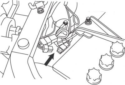
Figure 8.8. Location of the 5th gear sensor connector, which is part of the fuel-efficient driving…

Figure 8.8. Location of the 5th gear sensor connector, which is part of the fuel-efficient driving mode indicator system


Disconnect the connector from the 5th gear shift sensor (located next to the battery) and check again (figure 8.8). The indicator lamp should not light. Connect the connector.

Over-throttle warning light


This test will require a vacuum pump and a vacuum gauge.
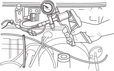
Figure 8.9. Checking the vacuum switch of the fuel economy indicator system

Figure 8.9. Checking the vacuum switch of the fuel economy indicator system


Disconnect the vacuum hose from the switch and connect a vacuum pump and vacuum gauge in its place (figure 8.9). Turn on the ignition. An assistant will be needed to observe the indicator lamp while the vacuum in the switch is increasing. The control lamp should light up at a vacuum of 0 to 120 mm Hg and go out as the vacuum increases.
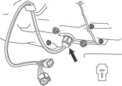
Figure 8.10. Location of the 5th gear shift sensor

Figure 8.10. Location of the 5th gear shift sensor


On pre-1984 models, disconnect the connector from the 5th gear switch and retest (figure 8.10). The indicator lamp should not light. Connect the connector and vacuum hose to the 5th gear shift switch.

Replacement of components


Control lamps and indicators


Remove the instrument cluster glass and replace the indicator lamp.

Vacuum switch


Remove the vacuum hose and disconnect the connector from the switch. Remove the switch from the bracket on the car body.

Install the new switch, connect the hose and connector.

5th gear shift sensor


Along the wire route, locate the 5th gear engagement sensor and disconnect the connector from the sensor.

Remove the sensor from the gearbox. Please note that this may cause oil spillage.


Install the new sensor, connect the connector, then check the transmission fluid level.

Control unit


Access to the control unit is possible after removing the lower decorative trim of the instrument panel, switch panel or instrument cluster.
This article is available at: russian, bulgarian, belarusian, ukrainian, serbian, croatian, romanian, polish, slovak, hungarian
This text was checked by: Georgy Afanasyev
Share with friends on social networks:

Previous
Capella 3 and 4 » Emission reduction
Next

System for reducing toxicity when the throttle is abruptly closed
Automatic intake air temperature control system
Forced crankcase ventilation system
Lean fuel mixture control system when the vehicle is in neutral gear
Air injection system
Fuel economy system (since 1984)
Air injection system (since 1984)
Air valves — removal and installation (since 1984)
Reed valves — removal and installation (since 1984)
Air injectors — removal and installation (since 1984)
More articles on repairing other Mazda models
Fuel system of carburetor engines Mazda Familia 5 (1985-1989)
Fuel level indicator in the tank Mazda3 BK (2003-2009)
Fuel level indicator in the tank Mazda6 GG (2002-2008)
Fuel system of gasoline engines Mazda CX-5KE (2012-2017)
Technical data of the diesel fuel injection system Mazda 121 (3) (1996-2003)
Link in different formats to this article
Comments and feedback from visitors
No comments yet


How much will 45 + 32 ?


Capella 6 (1997-2005, petrol) 
  • General information
  • Introduction to guide
  • User manual
  • Troubleshooting
  • Maintenance
  • Power unit
  • 4-cylinder engines
  • 6-cylinder engines
  • Engine overhaul
  • Cooling and ventilation
  • Power and exhaust systems
  • Engine electrics
  • Control system
  • Transmission
  • Mechanical gearbox
  • Automatic gearbox
  • Clutch and drive shafts
  • Chassis
  • Brake system
  • Car suspension
  • Steering
  • Body
  • Exterior (external elements)
  • Interior (internal elements)
  • Doors, windows and locks
  • Electrical equipment
  • Equipment and devices
  • Electrical circuits
Capella 5 (1991-1997) 
  • General information
  • User manual
  • Maintenance
  • Helpful hints
  • Power unit
  • Petrol engines 1.6 and 1.8
  • Petrol engines 2.0
  • 2.5 petrol engines
  • Overhaul engines 1.6 and 1.8
  • Overhaul engines 2.0 and 2.5
  • Diesel engine 2.0
  • Engine electrics
  • Cooling system
  • Air conditioner
  • Carburetor Nikki 30/34
  • Power system (1.6 and 1.8)
  • Power system (2.0 and 2.5)
  • Control system
  • Transmission
  • Mechanical gearbox
  • Automatic gearbox
  • Clutch and axles
  • Chassis
  • Brake system
  • Suspension and wheels
  • Steering
  • Body
  • Exterior (external elements)
  • Interior (internal elements)
  • Doors and windows
  • Electrical equipment
  • Equipment and devices
  • Electrical circuits
Capella 4 (1987-1992) 
  • General information
  • Introduction to manual
  • Vehicle specifications
  • Power unit
  • Engine repair
  • Lubrication system
  • Cooling system
  • Fuel system (carburetor)
  • Fuel injection (FE)
  • Fuel injection (DOHC)
  • Fuel system (diesel)
  • Ignition system
  • Transmission
  • Clutch
  • Gearbox
  • Drive shafts
  • Chassis
  • Front suspension
  • Rear suspension
  • Steering system
  • Brake system
  • Electrical equipment
  • Equipment and devices
  • Electrical circuits
Capella 3 and 4 (1982-1992) 
  • General information
  • User manual
  • Maintenance
  • Power unit
  • Gasoline engine
  • Engine overhaul (gasoline)
  • Diesel engine
  • Cooling and heating
  • Supply system
  • Ignition system
  • Emission reduction
  • Transmission
  • Clutch
  • Mechanical gearbox
  • Automatic gearbox
  • Drive shafts
  • Chassis
  • Brake system
  • Suspension and wheels
  • Steering
  • Body
  • Exterior (external elements)
  • Interior (internal elements)
  • Electrical equipment
  • Equipment and devices
  • Power devices
  • Electrical circuits
Capella 3 (1982-1992, petrol) 
  • General information
  • User manual
  • Maintenance
  • Troubleshooting
  • Late models
  • Power unit
  • Engine in car
  • Engine overhaul
  • Cooling and heating system
  • Fuel and exhaust system
  • Engine electrical system
  • Emission control system
  • Transmission
  • Mechanical gearbox
  • Automatic gearbox
  • Clutch and drive shafts
  • Chassis
  • Brake system
  • Suspension and wheels
  • Steering
  • Body
  • Exterior (external elements)
  • Interior (internal elements)
  • Electrical equipment
  • Equipment and devices
  • Lighting and lamps
  • Electrical circuits
MazBook.ru © 2018–2026 · Mobile version · Articles and news · Sitemap: EN BG BY UA RS HR RO PL SK HU · Feedback · Site search · Add to bookmarks Familia 5 (BF) · Familia 6 (BG) · Capella 3 (GC) · Capella 3 and 4 (GC) · Capella 4 (GD) · Capella 5 (GE) · Capella 6 (GF) · Mazda3 BK · Mazda6 GG · CX-5KE · Mazda 121 (3) · Mazda BT-50 (1) ·
By continuing to use the site, you agree to the use of cookies 🔐