


The system consists of a flame arrester valve and a pneumatic shock absorber mounted on the carburetor (on models with manual transmission), throttle control.
A sign of a faulty pneumatic valve is the immediate closing of the throttle valve when the accelerator pedal is suddenly released. Flame arrester failure may manifest itself in the form of backfires from the burning mixture and continued engine operation after the ignition is turned off.
Technical condition check
Flame arrester
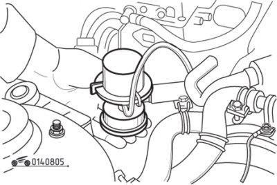
Figure 8.5. Checking the flame arrester valve
Start the engine and place your hand on top of the flame arrester (figure 8.5).
Caution! Increase engine speed to 3000 min⁻¹
, then quickly release the throttle. The flame arrester is working properly if you can feel the air flow coming from it.
Let the engine idle. Disconnect the air hose from the flame arrester and close the hose inlet. If the engine idle speed after disconnecting the air hose differs significantly from the speed before disconnection, there is a leak and the flame arrester should be replaced.
Pneumatic shock absorber
Quickly move the throttle lever away from the air shock absorber and check the speed of movement of the air shock absorber piston rod along its entire length. Release the throttle lever and ensure that after contacting the air spring rod, the lever smoothly returns to the idle position.
To adjust the air shock absorber, start the engine, warm it up and let it idle.
Connect the tachometer. While slowly increasing engine speed, check that the air shock absorber rod moves away from the throttle lever at approximately 2200 rpm. To adjust, loosen the lock nut and tighten the air shock absorber further.
If after adjustment the air shock absorber does not operate as intended, replace it.
Replacement of parts
Flame arrester
Remove the air supply hose and, by pressing the latches, disconnect the flame arrester from the bracket.
Install the new flame arrester into the bracket and connect the air supply hose.
Pneumatic shock absorber
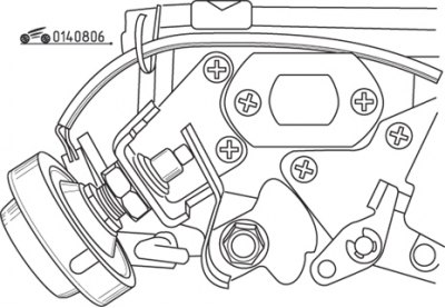
Figure 8.6. Pneumatic shock absorber with fastening and drive elements
Loosen the lock nut and remove the air shock absorber from the bracket (figure 8.6).
Install the new air shock absorber and adjust it as described above.