


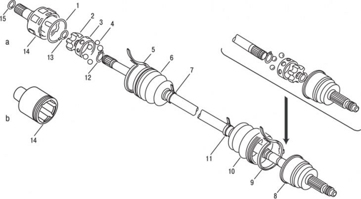
Figure 9.28. Drive shaft: a – left side; b – right side; 1, 12, 15 – retaining rings; 2 – hinge sleeve; 3 – separator; 4 – ball; 5, 7, 9, 11 – clamps; 6 – protective cover; 8 – inner CV joint; 10 – protective case; 13 – thrust ring; 14 – outer CV joint housing
The drive shafts transmit torque from the engine, gearbox and differential to the front wheels (figure 9.28). In the gearbox housing, the drive shafts are attached with splined connections to the differential axle gears. The splined end of the inner joint of the drive shaft is fixed in the axle gear by a spring retaining ring. When installed, the retaining ring is compressed, entering the groove of the shaft. Once the shaft is fully seated in the differential axle gear, the retaining ring is released and locks the splined tip from axial movement. The outer joints of the drive shafts are attached to the hubs of the front wheels, which are mounted on bearings. The shaft is fastened to the hub with a nut.
The drive shafts are the same length with an intermediate shaft located between the gearbox and the right drive shaft. The CV joints are protected by rubber boots, which are secured with clamps and prevent contamination of the CV joints with water and dirt.
Covers should be inspected periodically for signs of damage, lubricant leaks or cuts.
Damaged CV joint boots must be immediately replaced with new ones, otherwise the CV joints may be damaged. Replacing the cover involves removing the drive shafts. The most common signs of a worn or damaged CV joint, other than lubricant leaks, are clicking noises when turning corners, a humming sound when accelerating from coasting, or vibration at high highway speeds.