
Ignition systems with distributor
Examination
1. Turn the ignition key to the OFF position.
2. If the ignition coil is in the distributor, remove the distributor from the engine (see paragraph 9).
3. If the coil is outside the distributor, in the engine compartment, disconnect the electrical connector of its primary winding.
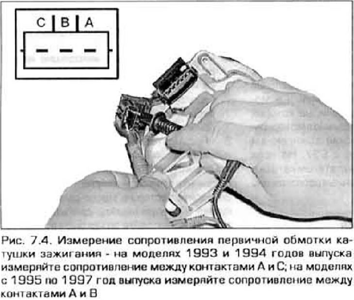
4. Measure the resistance of the primary winding of the coil with an ohmmeter and compare the result with technical data (pic. 7.4).
5. Measure the resistance of the secondary winding between the high voltage output of the coil and the positive terminal of the primary winding. Compare the resulting value with technical data (pic. 7.5).
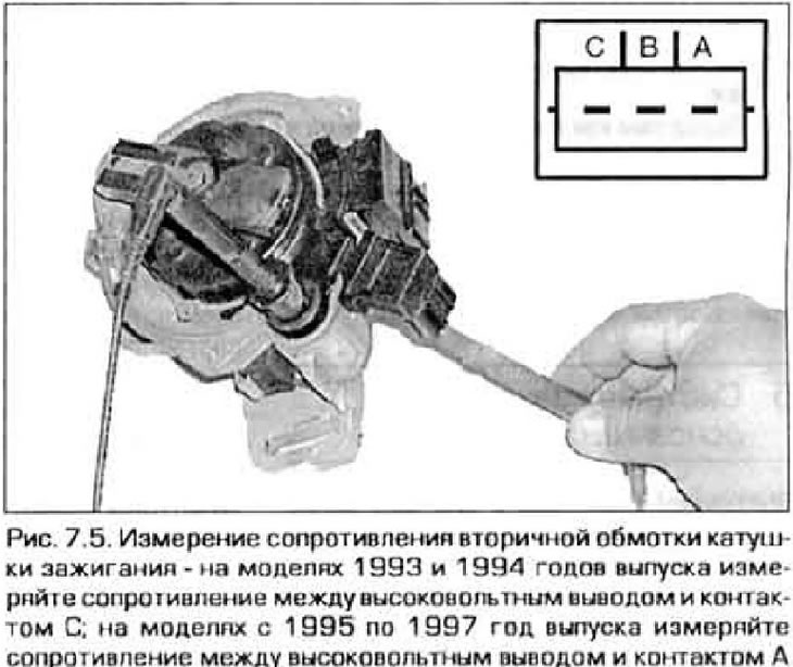
6. The measured resistance values may differ slightly from those indicated in technical data depending on coil temperature. IN Technical Data resistance values are given for a temperature of 21°C.
7. If the resistance of at least one of the windings is significantly different from the required one, replace the coil.
Replacement
8. Disconnect the negative cable from the battery.
Warning. If your vehicle's audio system is equipped with an anti-theft protection, be sure to disconnect the battery before disconnecting the battery. that you know the unlock code.
9. If the ignition coil is located inside the distributor, then. as the manufacturer assures, it is possible to replace the coil only assembled with the distributor as a single unit. However, before you decide on such a replacement, still look for a coil on sale separately from the distributor - you may be lucky.
10. If the coil is located separately from the distributor, disconnect the connectors from it, unscrew the fixing nuts and remove the coil.
11. Installation is carried out in reverse order.
Ignition systems without distributor
Examination
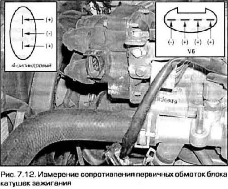
12. Disconnect the electrical connector of the coil unit (pic. 7.12). Measure the resistance between ground contact (-) and each of the positive pins of the connector. If the measured values are outside the limits specified in Technical Data, replace the coil pack.
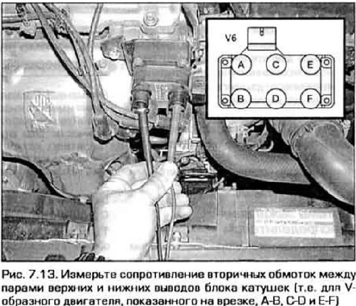
13. Mark the high voltage wires so as not to mix them up when reinstalling, and disconnect them from the coil pack. Measure the resistance between each pair of leads (fig.7.13). Compare the measurement results with the values given in Technical Data. If at least one of the measured values is out of range, replace the coil pack.
Replacement
14. Mark the high voltage wires and their terminals on the coil pack so as not to confuse them when reinstalling. Disconnect the connector wires from the old block.
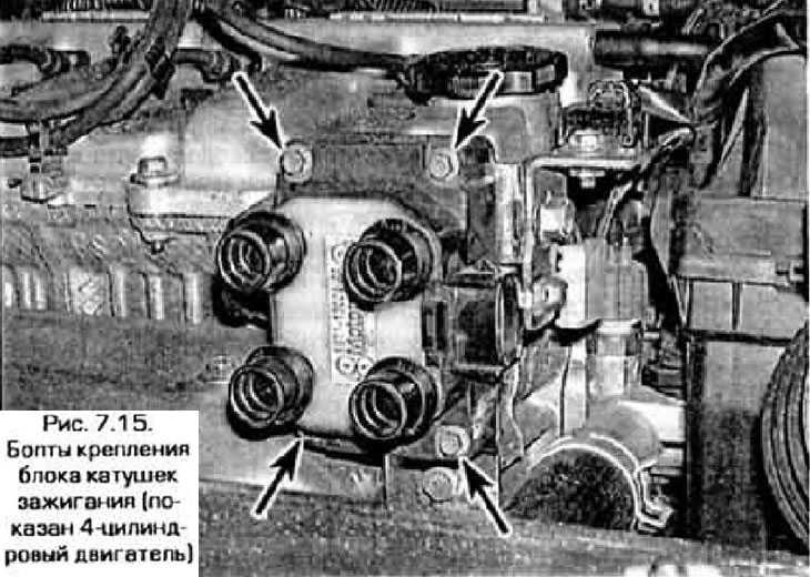
15. Turn out bolts of fastening of the block of coils and remove it from the engine (pic. 7.15).
16. Installation is carried out in reverse order.